Motor Magnetic Components

Drawing-based magnetic components for rotary and linear motor designs, organised by magnetic layout and installation interface.
Linear, stator/rotor, surface-mounted rotor and radial PM bearingChoose the structure for review.
Layout and mating interfacesDefined for the motor assembly.
Positioning and bondingRoute reviewed for the component geometry.
Cylindrical motor magnetic components for rotor integration – NEOLUNE MAGNETS.

Product examples

Browse the four component groups by structure.
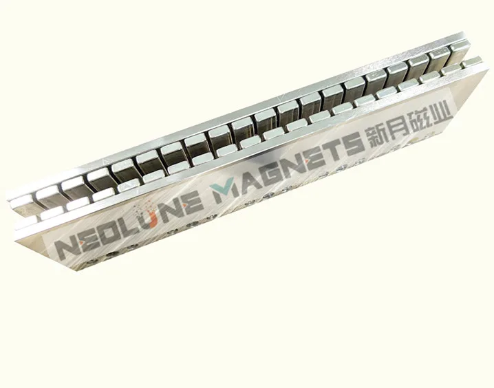
Linear Motor Components

Linear motor magnetic components with a segmented track on a channel carrier – NEOLUNE MAGNETS.
Linear magnet row mounted in a channel-shaped carrier.

Stator & Rotor Components

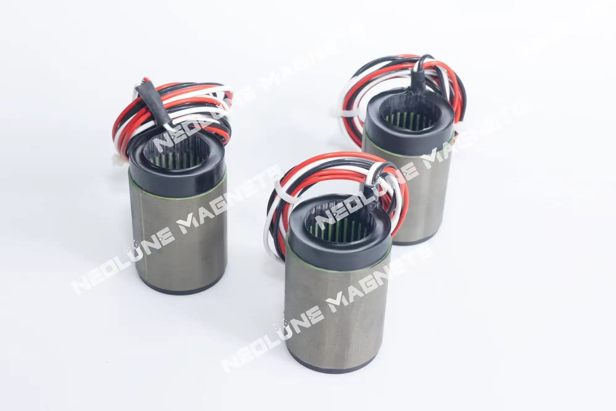
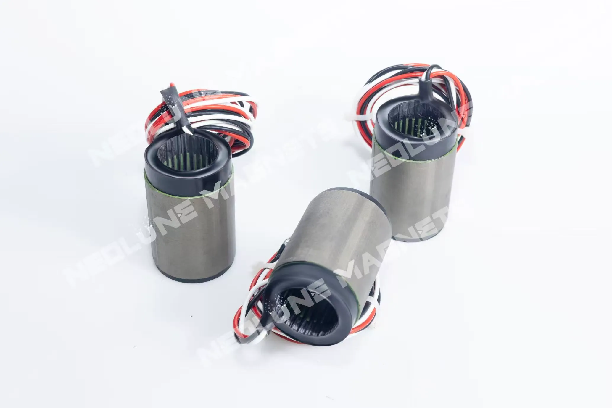
Cylindrical stator components with leads for electric motor integration – NEOLUNE MAGNETS.
Cylindrical stator components with leads around the open ends.
Open-end and side views of stator components for electric motors – NEOLUNE MAGNETS.
Stator housings shown upright and from the open end.
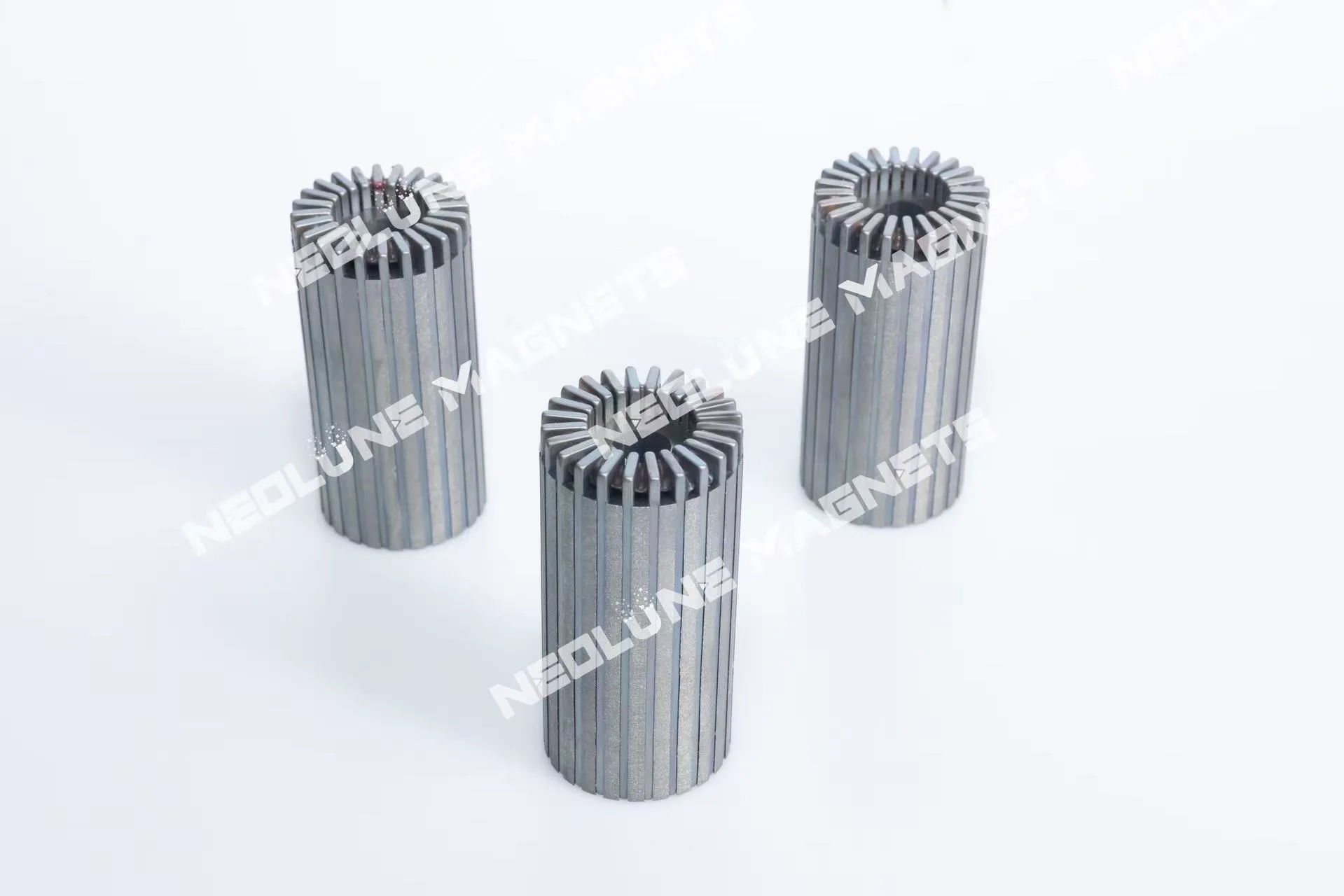
Segmented cylindrical motor magnetic components for rotor integration – NEOLUNE MAGNETS.
Cylindrical rotor components with segmented outer structures.
Bore and side views of motor magnetic components for rotor integration – NEOLUNE MAGNETS.
Rotor forms showing the central bore and outer segments.
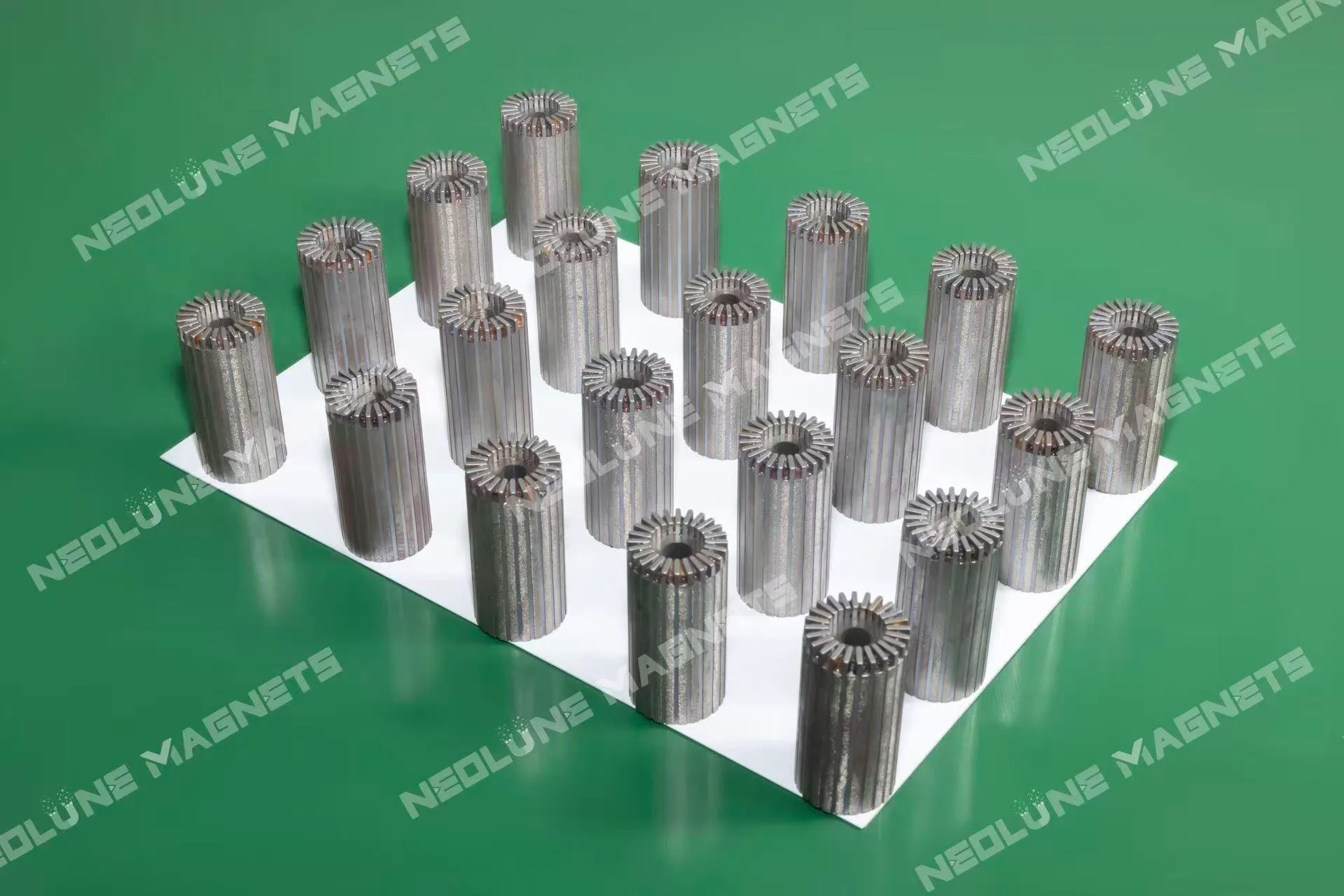
Cylindrical motor magnetic components arranged for rotor integration – NEOLUNE MAGNETS.
A group of upright cylindrical rotor components.
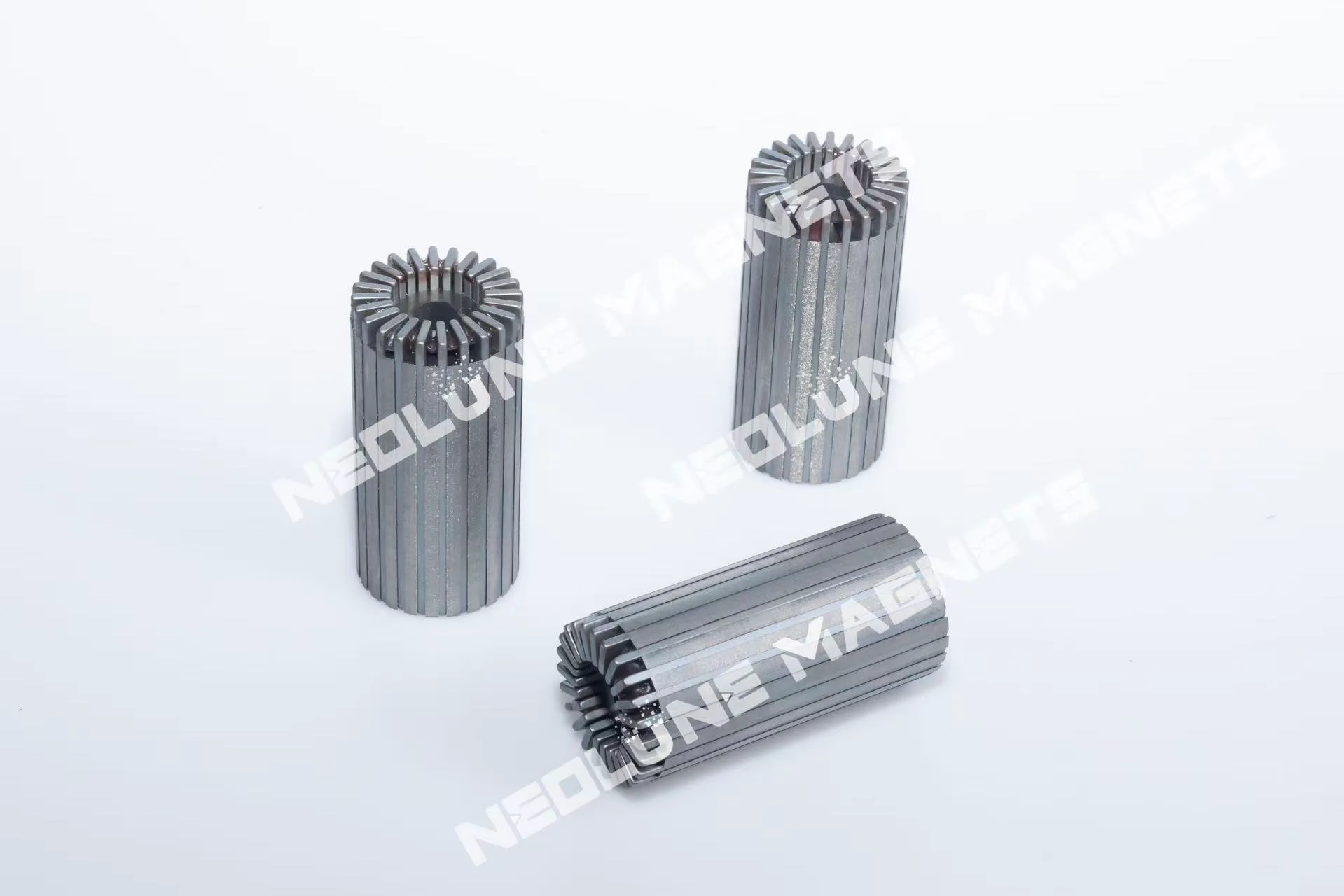
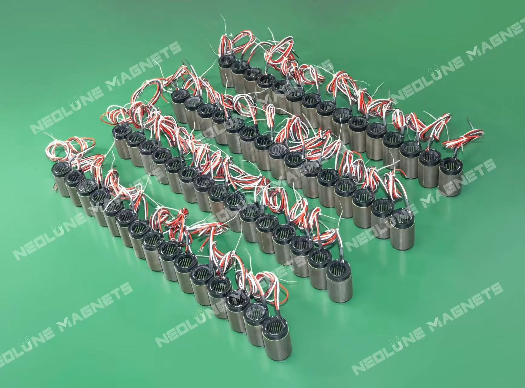
Cylindrical motor components with exposed leads for electric motor integration – NEOLUNE MAGNETS.
Rows of cylindrical components with exposed leads.

Surface-mounted Rotor Assemblies

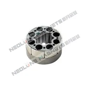
Surface-mounted rotor motor magnetic components with a ring of openings – NEOLUNE MAGNETS.
Short cylindrical assembly with a ring of openings.
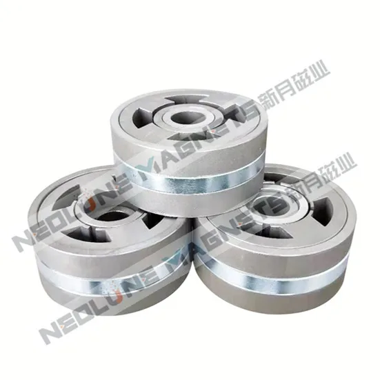
Surface-mounted rotor motor magnetic components with magnets around the perimeter – NEOLUNE MAGNETS.
Circular rotor form with magnets around the perimeter.
Ring-shaped motor magnetic components for surface-mounted rotor integration – NEOLUNE MAGNETS.
Ring-shaped assembly showing its central bore and outer segments.

Inner-rotor (Radial) Permanent-magnet Bearings

Ring-shaped radial permanent-magnet bearing components for motor integration – NEOLUNE MAGNETS.
Ring assemblies with central bores and visible internal segments.

Required engineering inputs

Start with the component type and the interfaces that locate it in your motor.

Component structureIdentify linear, stator/rotor, surface-mounted rotor or inner-rotor radial PM bearing.
Envelope and fitProvide dimensions, datums and mating shaft, housing or carrier details.
Magnetic arrangementState the pole layout, working air gap and target magnetic-field requirements.
Operating conditionsProvide temperature, speed or motion conditions and relevant mechanical requirements.
AcceptanceSpecify critical dimensions, magnetic checks and the required inspection or record scope.

Dimensions, materials, assembly interfaces and acceptance conditions are confirmed for the project. Operating speed, load and performance targets are engineering inputs, not universal component ratings.

Get a Quote

What to send us

  1. Component type and drawing revision
  2. Mating interfaces and assembly envelope
  3. Magnetic layout and working air gap
  4. Temperature and motion conditions
  5. Acceptance requirements and quantities

Review the installation

The component layout, magnet selection, coating and positioning requirements are reviewed together with the motor's mating parts.

Assembly interfaces and checks

Review magnetic layout
Magnetic-circuit simulation can support the selection of magnet grade, shape, coating and operating conditions.
Position and bond
The assembly approach is reviewed for rotor spacing, linear-track positioning and component dimensions.
Define inspection scope
Agree dimensional and magnetic checks, coverage and batch record content for the selected component.

Prototype to production

Prototype
From 1 set
Sample schedule
Typically 5–8 working days for mature drawings; 7–15 working days for new design and tooling
Production MOQ
Confirmed by specification; production typically 15–30 working days, depending on quantity
Packaging
Magnetic shielding and protective packaging

Sample and production schedules depend on component type, design, tooling and quantity. Timing starts after drawing confirmation and receipt of sample payment.

Explore application requirements before selecting the component layout.

Discuss motor magnetic components

Share the component type, installation drawing, magnetic layout and operating conditions.

Get a Quote

Submit your inquiry using the form. Email drawings to sales@neolune.com.