Engineering
Magnetic Design & Assembly Engineering
We develop drawing-based magnetic components for motor, robotics and automation equipment, from magnetic circuit design to assembly.
What to send
- Drawing
- Component geometry, dimensional limits, mounting interfaces and the working air gap.
- Magnetic field target
- Target field in the working region and the required magnetisation direction or array layout.
- Operating conditions
- Application, working temperature, speed where relevant, and the surrounding environment.
- Quantity
- Prototype quantity, expected production quantity and the acceptance requirements to discuss.
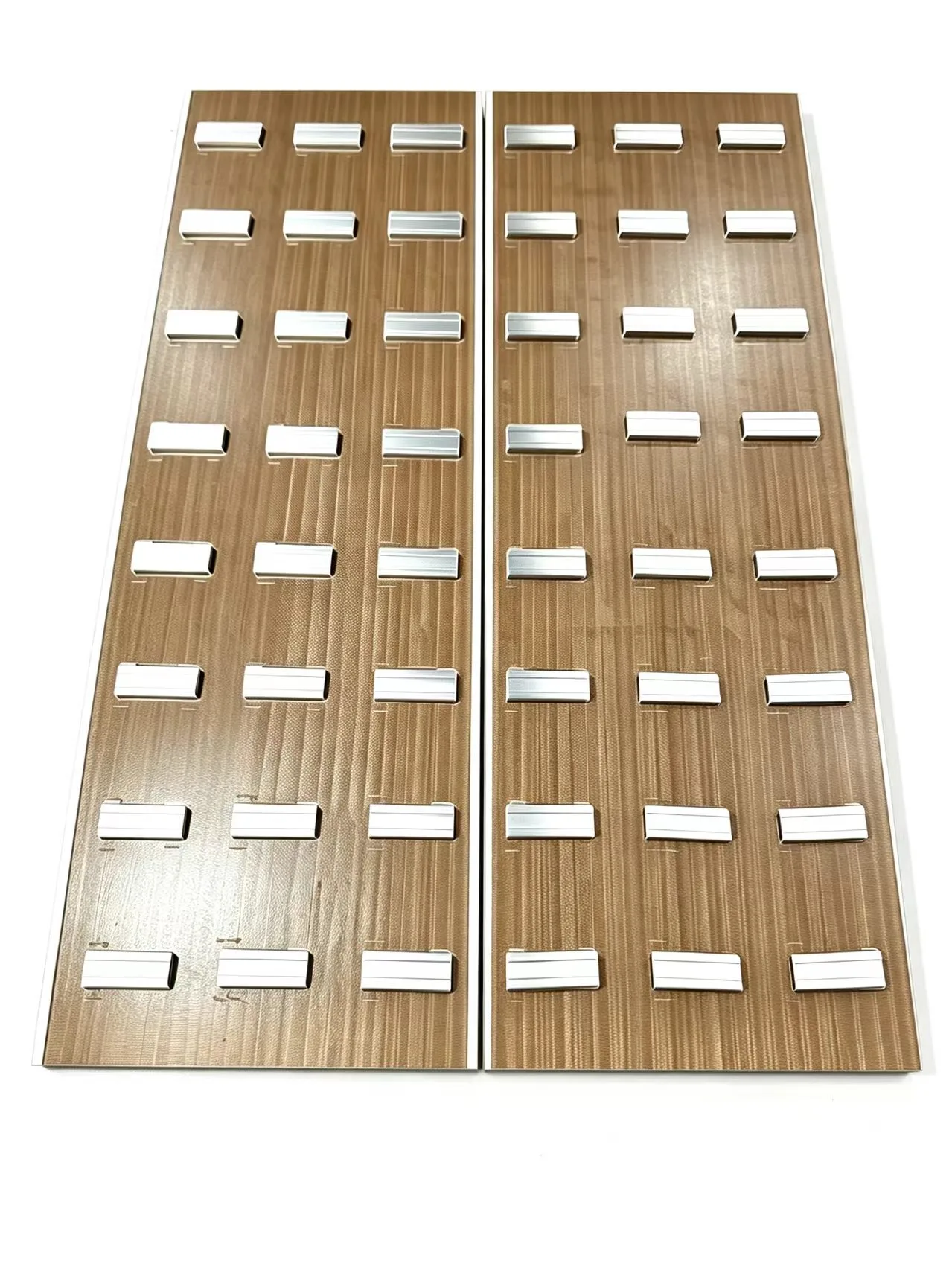
Drawing review and magnetic design
We can review magnetic circuits and perform magnetic simulation to support component design and material selection.
- Geometry and interfaces
- Review the drawing, available space, air gap and the interfaces that locate and restrain the assembly.
- Magnetic circuit
- Use magnetic design and simulation to assess the array layout, segmentation and magnetisation angles against the field target.
- Material and assembly choices
- Discuss magnet grade, coating and assembly route against temperature, component geometry and production quantity.
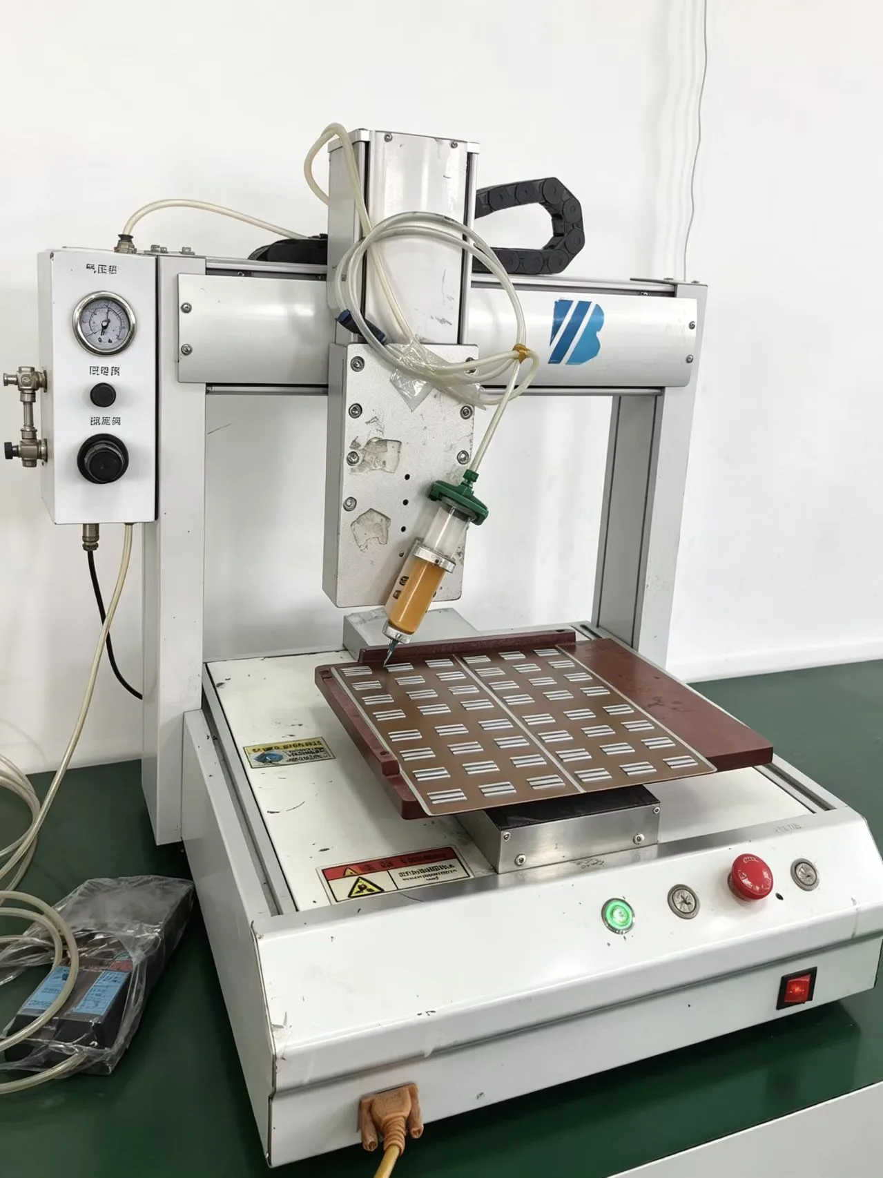
Machining to curing
The assembly route follows the component drawing, magnetic layout and agreed production requirements.
Machining
Prepare the magnet shapes and dimensions specified by the component drawing.
Sorting
Select and group magnets for the required magnetic layout and agreed assembly conditions.
Positioning
Use assembly fixtures to locate magnets and control their orientation and spacing.
Bonding
Apply adhesive and assemble the magnets with the required restraint. Bonding before or after magnetisation depends on size, structure and batch quantity.
Curing
Complete the agreed adhesive curing process before the subsequent inspection and delivery stages.
Prototype to production
Paid samples can start from one set. The route and timing depend on the drawing, tooling and quantity.
- Mature drawing samples
- 5–8 working daysTypical timing for an established drawing, subject to design and tooling requirements.
- New design and tooling
- 7–15 working daysTypical sample preparation including simulation and tooling for a new design.
- Production
- 15–30 working daysTypical lead time, subject to the specification, tooling and order quantity.
Timing starts after drawing confirmation and receipt of sample payment.
Production MOQ is confirmed by specification. The final schedule is agreed for the order.
Discuss your engineering requirements
Share your drawing, magnetic field target, operating conditions and quantity to begin the component review.
Submit your inquiry using the form. Email drawings to sales@neolune.com.