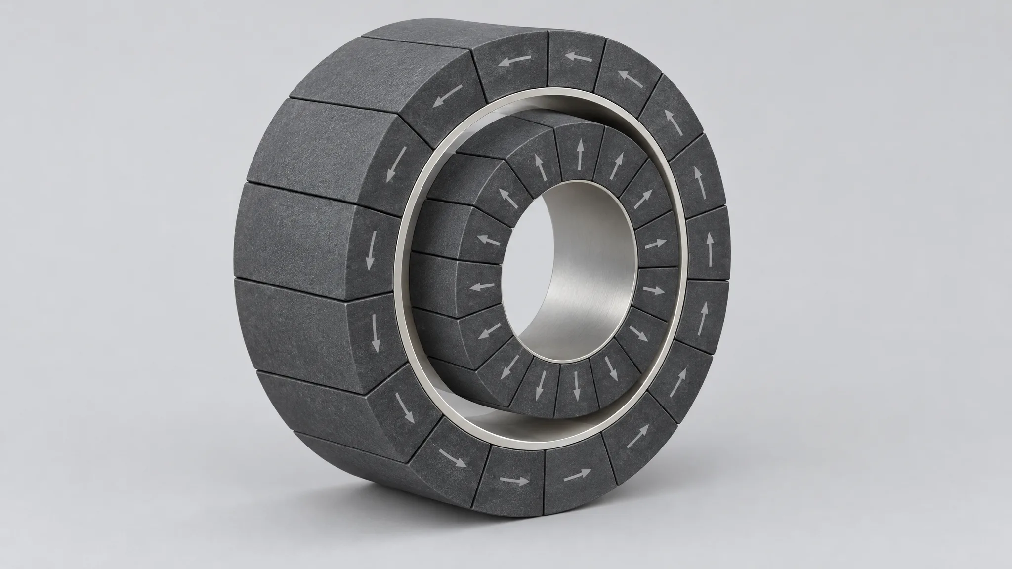
Magnetic Couplings: Sizing the Magnet Array Across the Containment Wall
How the containment wall, the gap stack and the pole count set a coupling's field, and what a matched pair of arrays has to prove before it ships.
How a small magnet array becomes one installable part: sorting, fixturing, adhesive and cure, the conditional ±0.05 mm, and the batch checks that prove the result.
Articles in this topic ↓Robot joint magnets and the small arrays inside 3C equipment run into the same problem: the space is so tight that most of the tolerance budget is spent before anything is made. A better grade of magnet rarely fixes that. What fixes it is a finished assembly — magnets sorted, positioned in a fixture, bonded, cured and checked — that goes onto the shaft or into the housing as one part.
We build that assembly as the product, and what follows is what the part has to have settled before the build is worth starting.
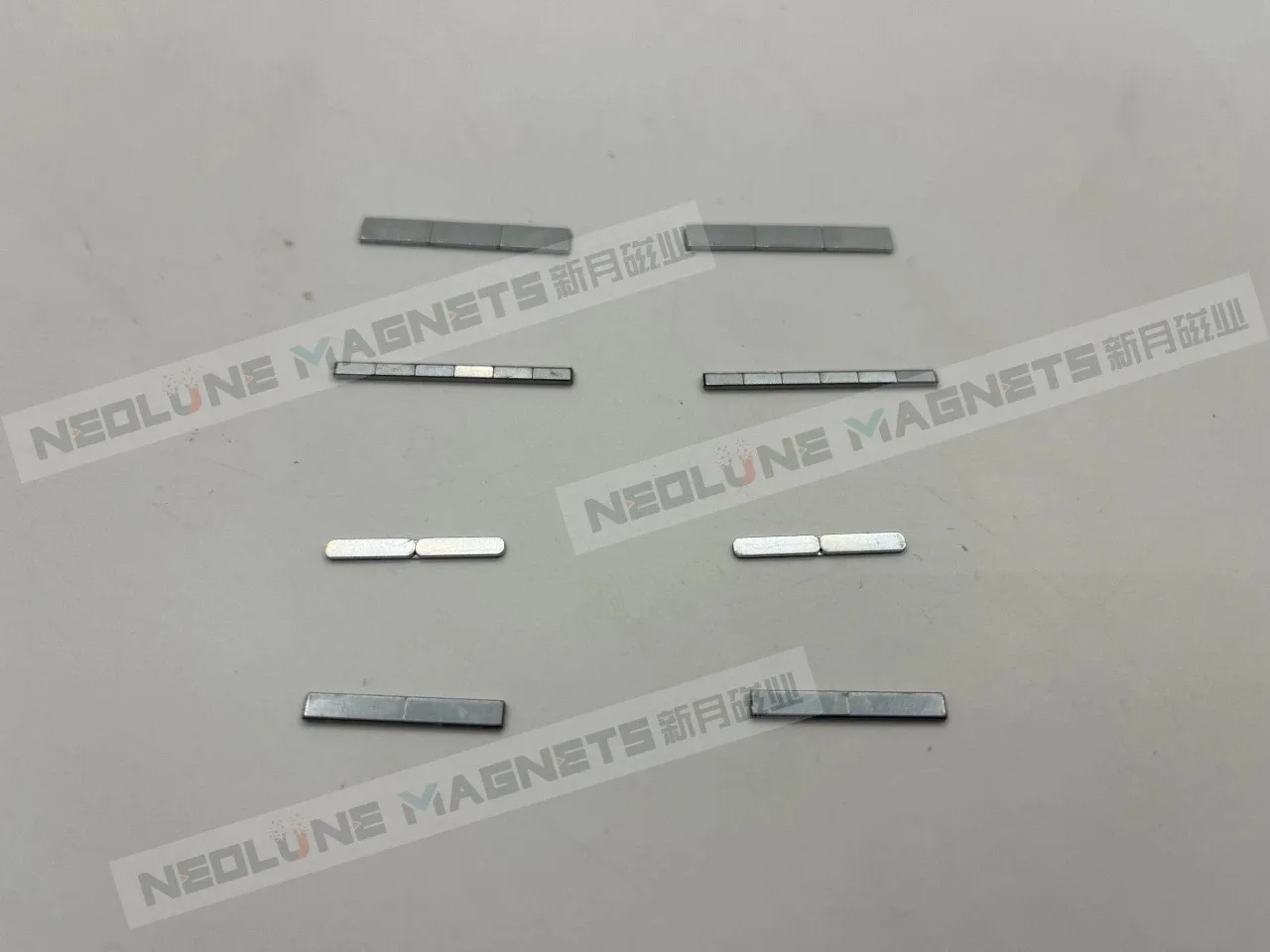
It is one finished component: magnets arranged to a layout, held on a carrier or a mounting face, bonded and cured, with the outside geometry checked before it ships. It installs on the fitting line; it is not built there.
The difference is easiest to see side by side.
| A loose magnet | An assembly for this class | |
|---|---|---|
| Where the tolerance attaches | the magnet's own dimensions | the position of each pole against the datum the machine locates on |
| What decides batch consistency | the magnet batch | the fixture, the adhesive and the cure |
| What arrives with the order | magnets in a box | one part that fits the shaft or the housing |
Layout, magnet grade and coating are all open at the start of a project and all three close on the drawing. Once they are on it, the arrangement is our problem rather than an assembly step on your line, which is the whole reason the part exists. Our 3C magnetic components are built this way.
In a robot, there are four directions we keep in front of a joint design: the drive inside the joint, torque carried through a sealed wall, a bearing that supports a rotor without contact, and the feedback that tells the controller where the joint is. In a 3C device the same class of part does the jobs a mechanism does worse — alignment, a short magnetic drive, a closure that has to feel the same every time.
Both lists are where the questions start, not a record of who we have supplied. The applications page carries them as selection reference for the sectors we discuss with customers.
Seven inputs, and the order matters less than having all seven.
Two of those decide whether a number means anything. A positional figure is measured from somewhere, so the datum has to be named. A field figure is measured across a gap, so the gap has to be given. Where either is left out, the drawing describes an intention rather than a part.
Four operations, in sequence, are what a batch of these parts is: sorting, positioning, bonding and curing.
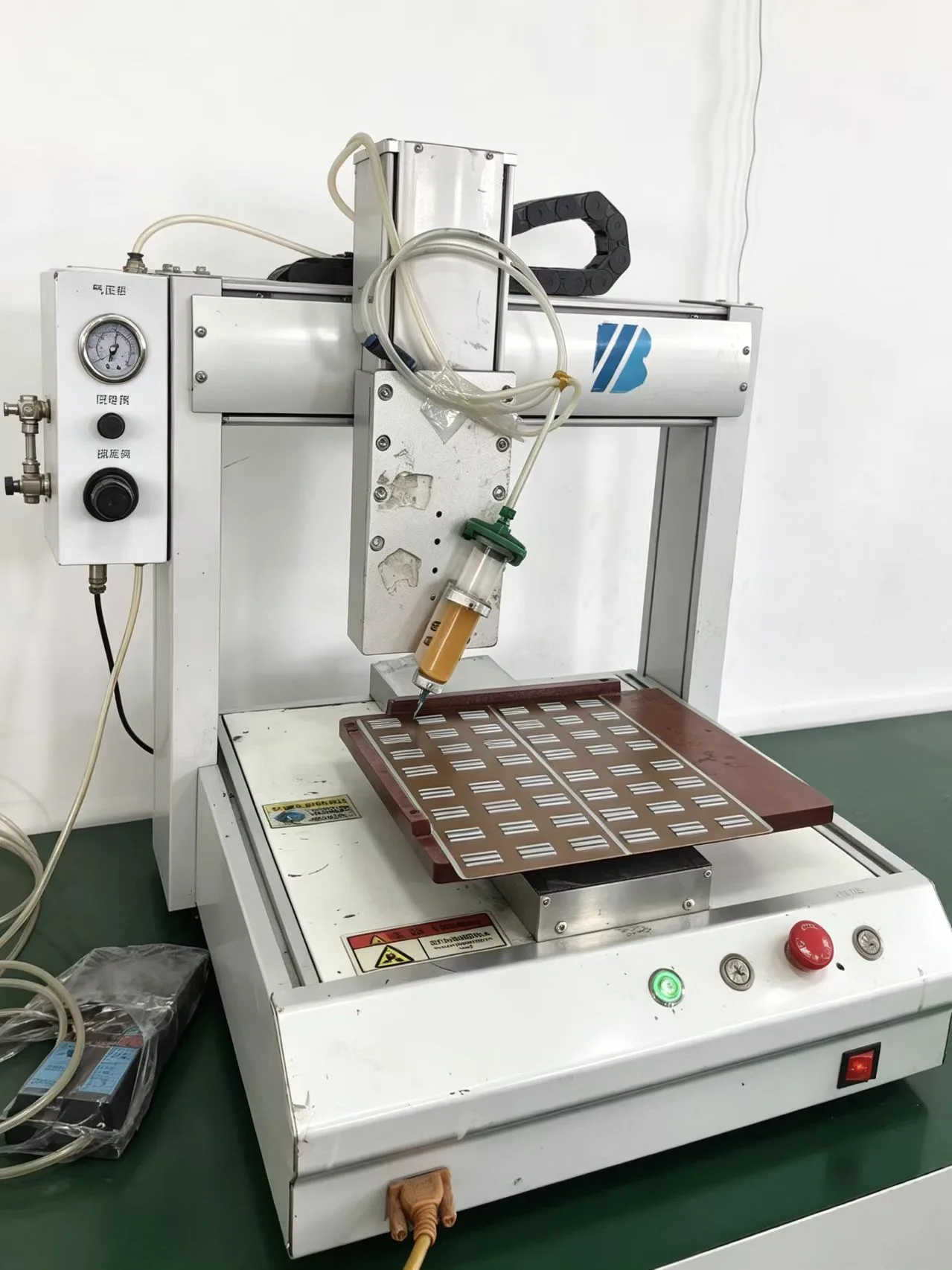
The magnets are sorted before they enter the fixture, so the parts that go into one assembly are the parts the drawing assumes. In the fixture each magnet is held where the drawing puts it. Adhesive is dispensed by machine rather than by hand, because the volume of the bond line is part of the geometry and it holds steadier when the same head lays it down. Then the part cures: curing is a step with its own conditions, and the placement that the fixture set is what the part keeps once the adhesive has reached them.
That sequence is the argument for buying the assembly rather than the magnets. The adhesive layer, the carrier and the placement each add their own error, and only the finished part shows the sum. A magnet machined to a tight tolerance can still make a poor assembly, and nothing on the magnet drawing would have said so.
It is an assembly accuracy we quote for 3C and robot-joint components: ±0.05 mm on the finished part, subject to the design agreed for the order. It is quoted for this class of component, and it applies to the dimensions named in the acceptance conditions rather than to every dimension on the part.
What the figure covers — the dimensions it applies to, the datum they are measured from, and the features outside it — is settled on the drawing. A bonded assembly has more than one surface worth measuring, and they do not all behave the same way.
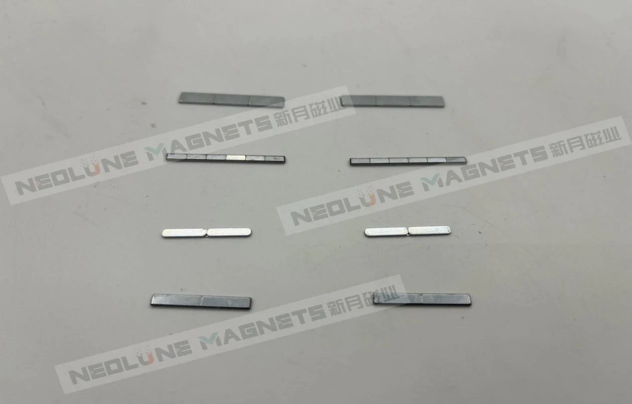
The class does not choose them; the working point does. Sintered NdFeB is the usual candidate where the envelope is small and the field has to be high — our range runs from N35 to N54, including the SH, UH and EH series — and SmCo where the temperature and the duty ask for it. What decides between them is the flux the gap needs at the temperature the part reaches in service, against the demagnetising field at the worst moment of the cycle.
Coating is a separate decision taken from the environment. Nickel-copper-nickel and epoxy are the two routes we quote, and which one a part gets depends on what it meets inside the device rather than on the magnet inside it. Both are settled on the drawing, not after the sample.
Every check has a stage where it can still change something; after that it only sorts good parts from scrap. On these parts the sequence runs through the material, the machining, the coating, the finished component and the packaging.
Which of those run, on how many parts, how often, and what reaches the report is agreed per order, together with the acceptance limits and the measuring conditions. The quality page sets out how that scope is written.
From one set. A paid sample can start at a single set, with no minimum on the sample itself. A mature drawing typically samples in 5–8 working days; a new design that needs simulation and tooling usually takes 7–15, and production typically runs 15–30, depending on quantity. The clock starts when the drawing is confirmed and the sample payment is received, so the revision you send is the revision the timing belongs to.
Send the drawing with the seven inputs on it — envelope, datum and mating faces, pole layout, working gap and field, grade and coating, working conditions, and the acceptance scope — and the review begins with the part rather than with a catalogue number. Drawings and questions reach our enquiry desk, and the review that comes before a quotation sits with engineering.
How the containment wall, the gap stack and the pole count set a coupling's field, and what a matched pair of arrays has to prove before it ships.