A magnetic coupling is sized by the wall it has to cross. The duty gives a torque and a speed, the process gives the containment sleeve a material and a pressure requirement, and the two magnet arrays have to deliver the torque across whatever distance is left between them. Two decisions carry the result, and they are usually taken in different rooms: the field budget across the wall, and the build of the two arrays as a matched pair.
That order is not a formality. Settle the sleeve after the array and the gap the design assumed no longer exists, so the magnet count has to be derived again rather than trimmed.
What does the containment wall cost you in torque?
Every non-magnetic layer between the two magnet faces sits inside the magnetic gap, and the field that crosses it falls away faster than linearly with distance. That is the first number to fix, before a grade or a pattern is discussed.
NDFEBShapes' sizing guide for permanent magnetic couplings writes that gap as a sum: the inner clearance, the encapsulation, the containment can and the outer clearance, plus adhesive and coatings where they are present, with the released stack left room for runout, bearing wear, pressure deflection and thermal expansion. In a coupling the wall between the driving and driven parts is one term in that sum, and usually the largest one. Thickness at the wall is therefore paid for twice — once in the pressure duty it has to carry, and again in the magnet material the larger gap demands.
On a pump or a sealed actuator the sleeve is not yours to thin: its pressure duty, its material and its corrosion allowance belong to the equipment designer. What stays open is the rest of the stack, and that is where the budget is managed.
Radial ring or axial disc — which does the wall allow?
A disc pair faces across a flat wall; a coaxial pair crosses a sleeve that wraps around the inner rotor. Choose by the wall that can actually be built and by the space at the ends of the shaft.
The two forms differ mechanically. Magnetic Technologies' comparison of disc and coaxial couplings notes that the coaxial design finds its own centre and carries close to zero axial force, while the disc style carries a high axial force that has to be restrained by the bearings, and that the disc uses a simple flat barrier against the coaxial top-hat sleeve. A retained axial force is a bearing and housing decision, and it is much cheaper to take before the array is designed than after.
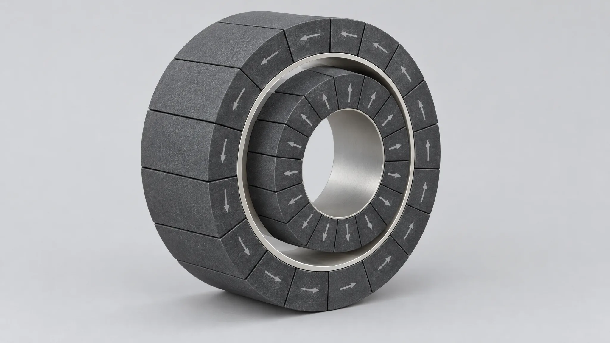
Where the form is coaxial the array is a ring, and the bore, the axial length and the mounting face settle its geometry first. The ring and arc arrays we build cover bores from φ10 mm to 400 mm with magnets no thinner than 2 mm, and the specification of any one ring still comes from its drawing.
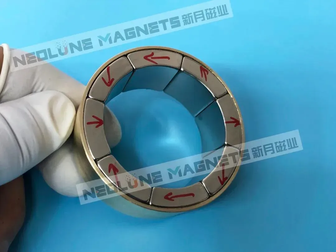
How many pole pairs does a magnetic coupling need, and how is the pattern laid in?
Enough to reach the torque inside the diameter you have, and no more than the gap and the sleeve will pay for. Pole count is not a free lever in either direction.
Two effects pull against each other. The same sizing guide writes the working field across the gap as falling roughly exponentially with distance, with a decay rate that rises with pole pairs and falls with gap radius — which is why adding pole pairs stops helping once the gap is large. The other effect is the sleeve: a conductive wall sees an alternating field, currents are induced in it, and the loss climbs with the frequency it sees, which pole pairs and speed raise together. A high pole count can add torque density in the diameter and give it back as drag and heat, so the pole count and the sleeve material belong in one conversation.
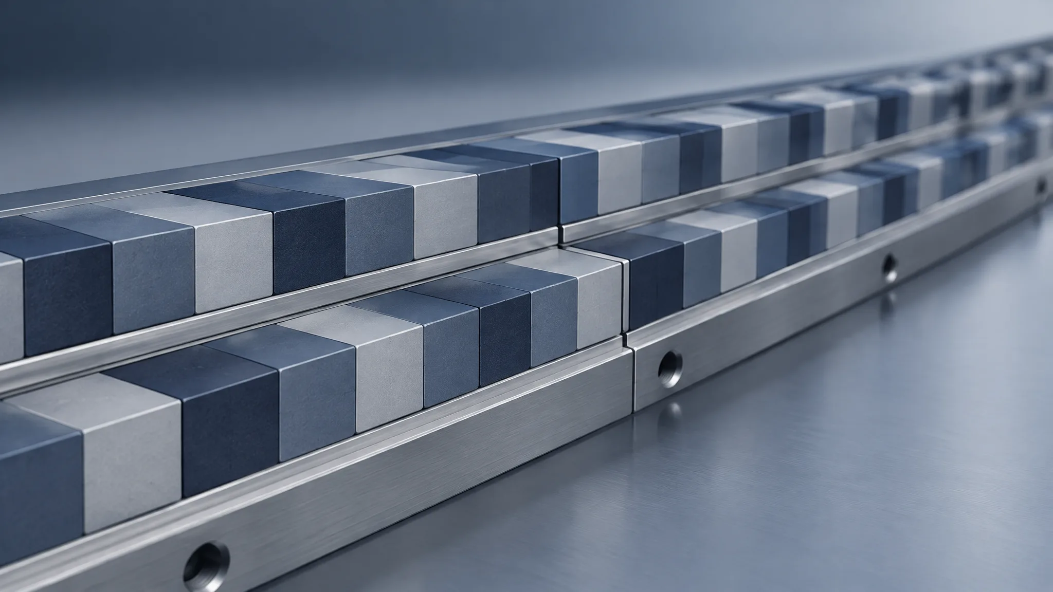
The pattern inside the ring is the other half, and there are two routes. Plain alternating poles are the simpler one: every segment is charged the same way, the pattern is cheaper to magnetise, and it leans on a yoke at the back to close the flux. A stepped magnetisation — each segment charged at an angle to its neighbour, the Halbach arrangement — is the alternative where that yoke has to go or where the back of the array must stay quiet, because it aims the field at the working side and pushes the back side down. Which one a coupling gets is an engineering decision rather than a preference: what the stepped pattern buys depends on the magnet circuit and the duty, and it is checked in simulation against the target gap flux density before anything is machined.
Where does the gap budget go before a grade is chosen?
Write the stack as one number on the drawing, and make the array answer to that number.
Five things usually sit in it:
- The containment sleeve, at the thickness its pressure duty requires.
- Any encapsulation over the wetted rotor, which is a corrosion barrier and a distance at the same time.
- Both running clearances, at the worst eccentricity the bearings allow.
- The coating on the magnets.
- What grows in service — runout, bearing wear, pressure deflection, thermal expansion — which the released stack has to leave room for.
Only then does the grade get chosen, and it is chosen hot. Transmitted torque falls as the magnets warm: Radialmagnet's coupling guide puts the reversible drop at roughly 12% for NdFeB across a 100 °C rise, which is enough to explain a coupling that held the load on a test bench and slips in a hot plant.
Read that figure as a torque figure that reverses when the heat comes off, not as a property of the grade, and 12% is where the grade conversation starts rather than where it ends: what a particular pair loses at its working point also depends on the circuit and on where its load line sits. The NDFEBShapes guide makes the compounding plain — if both rotors' effective fields fell to 90% of their reference values, its simplified field-product model predicts about 81% of the reference torque.
Our range runs from N35 to N54 including the SH, UH and EH series, with SmCo where continuous duty is above 150 °C, subject to the operating point. The grade follows the gap and the temperature rather than the other way round, which is the order the drawing review is built to work in.
What has to match across the pair?
The two arrays are one magnetic circuit, so the pair is matched rather than merely inspected. Per-magnet limits do not do this job: two rings can both be inside their individual tolerances and still differ, as a pair, from the pair that was designed.
Three things decide it:
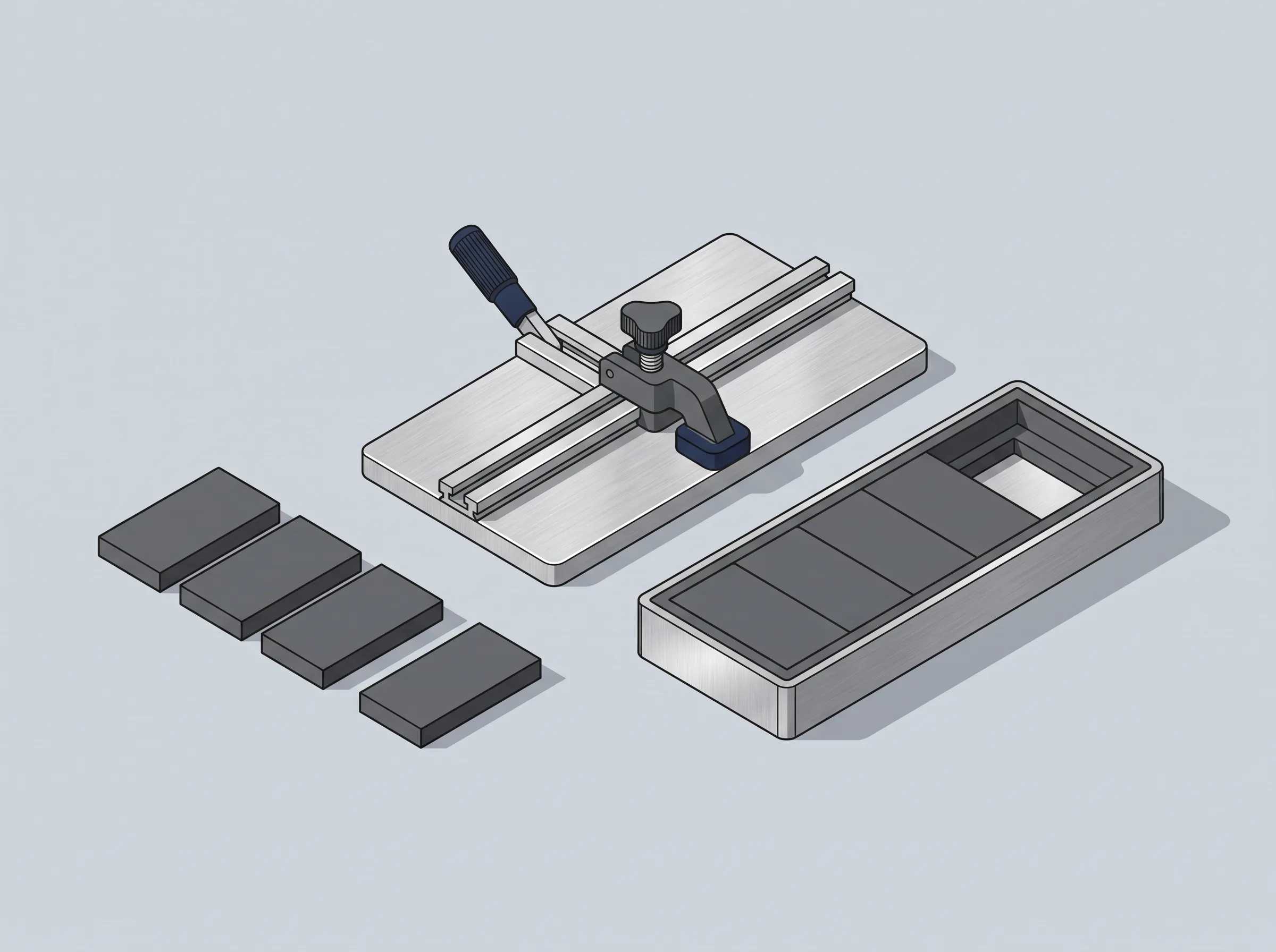
- Sorting across the set. The magnets are grouped before they enter the fixture, so the assembly holds the distribution the design assumed instead of whatever came out of the box.
- Angular placement. Each segment's position and its magnetisation direction are held by the fixture while the adhesive cures. Placement error arrives as error in the load angle, which is the margin a synchronous coupling runs on.
- Batch-to-batch spread. We hold the variation in gap flux density from batch to batch through tooling and magnet sorting, and the figure we discuss is ±3–5%, subject to the design and to the conditions agreed for the order. That figure is also why a replacement inner rotor ordered a year later is interchangeable only if the field acceptance went onto the drawing.
How is a magnetic coupling proved batch by batch?
By reading the field back off the finished part, not off the magnets that went into it.
A three-dimensional field scan of a finished array gives the gap flux density, how close the waveform comes to a sine, and its harmonic content. Dimensional, magnetic-moment and surface-field checks sit alongside it, with coating checks and a temperature-demagnetisation check where the order calls for one. Which of those run, on how many parts and how often, and what the report has to contain, are agreed for the order rather than carried over from the last one; the quality page sets out how that scope is written.
The scan is evidence about the field, not about the torque. Pull-out torque is the peak of the torque–angle curve at the hot operating point; the torque the pair transmits in service is that same curve read at the load angle it actually runs at, which is a smaller number and moves with the load. A measured torque-angle trace at temperature belongs to the coupling or pump builder's own test rig. What the field record does is make that test reproducible: it is the number a second batch, or a spare rotor, can be held to.
Two different numbers get called the torque in a coupling project, and writing them as one is how a sizing argument goes wrong. The first is the duty: the largest torque the process asks for — a flooded start, cold viscosity, a valve slam — and the speed at which it happens. The second is a floor the finished pair has to clear: the pull-out torque it must still reach at the hottest magnet temperature of the cycle, measured at the working gap. The floor sits above the duty by a margin, and that margin belongs to the order rather than to a table. The worked example in the NDFEBShapes guide, linked above, takes a peak startup demand of 78 N·m to a screening target of about 110 N·m through an illustrative factor of 1.4, and says in the same paragraph that the factor is not a standard requirement. We would rather settle the factor and its reason with you — what the acceleration needs, what the process does when the driven side stops, what the protection can see — than quote one that fits another plant.
The floor is a minimum, not the point where the coupling lets go. A pair that clears it can pull out higher, and only its measured torque-angle curve says by how much. A pair that clears it narrowly still meets the drawing — the margin is already inside the floor — but it has less left over above the duty the plant actually delivers, and that surplus is what a colder start, a changed viscosity or a worn bearing spends. When the load does reach the real pull-out, the coupling does not throttle — it lets go. A synchronous pair loses synchronism at once, the pole sets sweep past one another, and the driven side may slow, oscillate or stall while the driver keeps turning.
Two frequencies are in play and they are not the same one. Between the two rotors the pole patterns now pass each other at the speed difference between them — p times that difference, over 60 — where in normal running they do not pass each other at all; the reverse fields and the extra rotor eddy-current heating that come with that motion cut into the demagnetisation margin. The stationary can has its own problem and does not wait for a slip: with both rotors turning together it already sits in an alternating field at p times the running speed, which is why its loss is there in normal running. At decoupling, Radialmagnet's guide reports severe eddy heating almost immediately and shell damage possible within seconds — a containment breach on a hazardous fluid — and notes that the pair will not re-synchronise while the driver is at speed: the unit has to be stopped and restarted. How much that interval costs depends on the magnets, the geometry, the cooling and how long the event lasts, and there is no universal safe delay to design to.
None of that is a trip. Nothing in the coupling opens, signals or resets when it lets go, and whatever detects the slip — power monitoring, a temperature sensor on the shell, a comparison of the two speeds — is agreed as part of the installation rather than assumed from the magnet side.
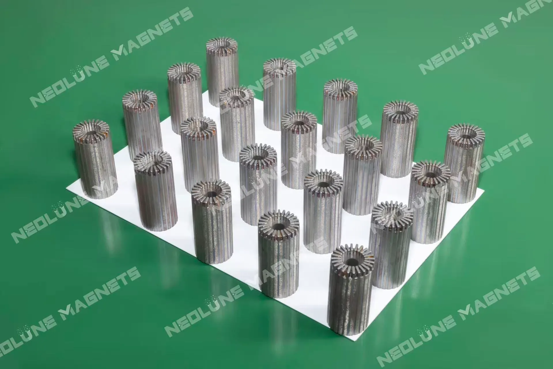
Underneath the field record sits a build decision that often surprises a coupling project. A complete ring can be bonded first and magnetised afterwards, which takes the repulsion off the assembly bench — but only while the finished ring fits the magnetiser cavity. Rings and patterns that do not fit are charged segment by segment and bonded under fixtures that hold the repulsion while the adhesive cures. Segment count, grade and magnetisation angles therefore cannot be settled apart from the route, because the pattern that is better magnetically may not be buildable as one ring.
The pair ships as finished assemblies: sorted, positioned, bonded, cured and checked, packed with magnetic shielding and protection against chipping, because the risk in transport is a broken corner rather than a lost field. An array of this kind is not made to be taken apart on a fitting line.
What do you send us to size one?
Seven inputs, and the drawing carries most of them:
- The worst-case torque — starting, cold viscosity, a transient — with the speed at which it happens.
- The target field in the working gap.
- The gap stack: sleeve material and thickness, encapsulation, both clearances.
- The envelope: inner bore, outer diameter, axial length.
- The magnet temperature at the worst point of the cycle.
- The pole count, if the drive has already fixed it.
- Prototype and production quantities, with the checks and the batch record the order has to produce.
From those, the array review comes back as a segment count, a grade and magnetisation angles against the target gap flux density. A paid sample can start from one set: a mature drawing typically samples in 5–8 working days, a new design with simulation and tooling in 7–15, and production usually runs 15–30, with the clock starting after the drawing is confirmed and the sample payment is received.
Send the drawing with those seven on it and the review starts from the design rather than from a catalogue number; drawings and questions reach our enquiry desk, and sales@neolune.com takes the files.