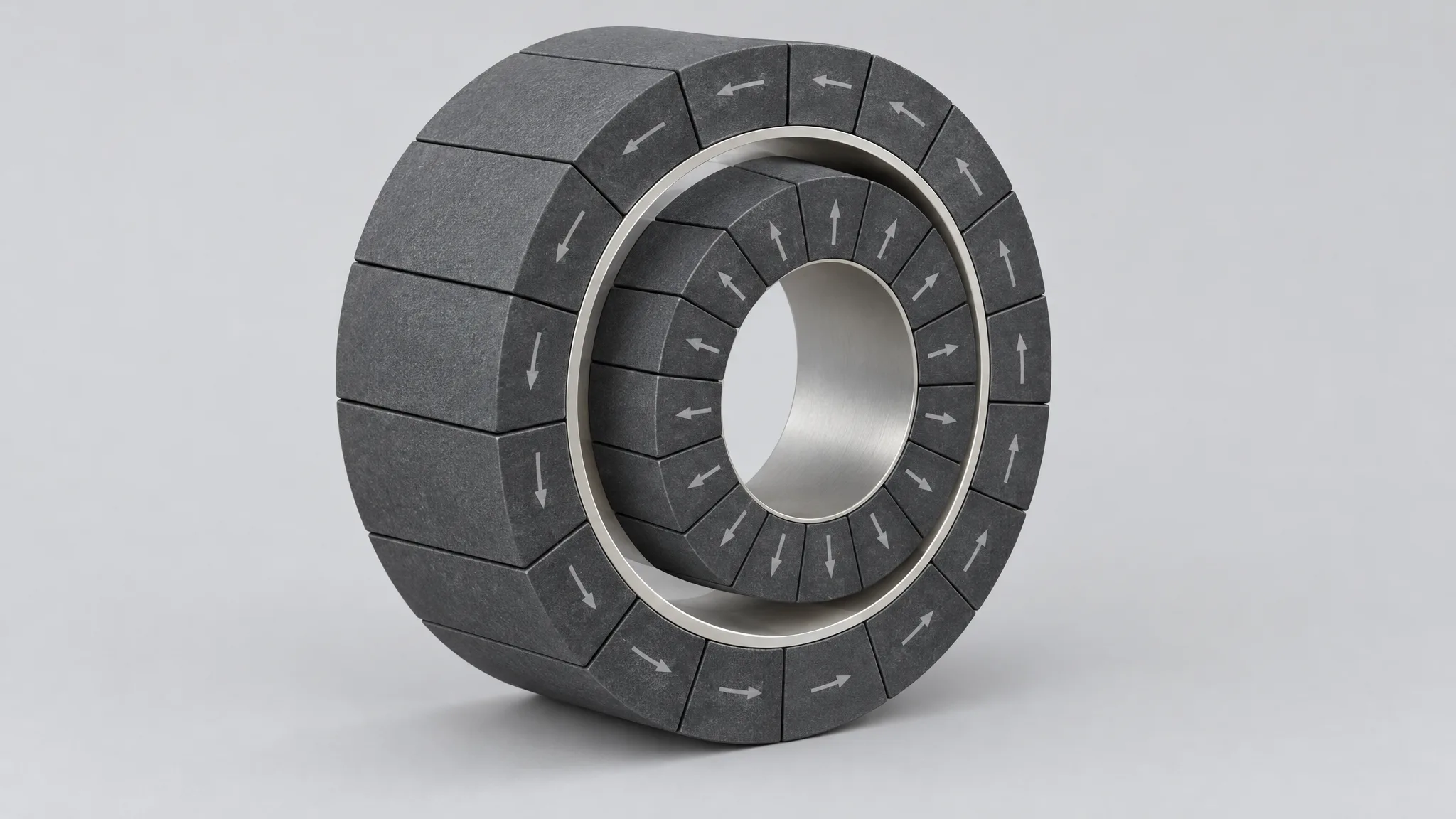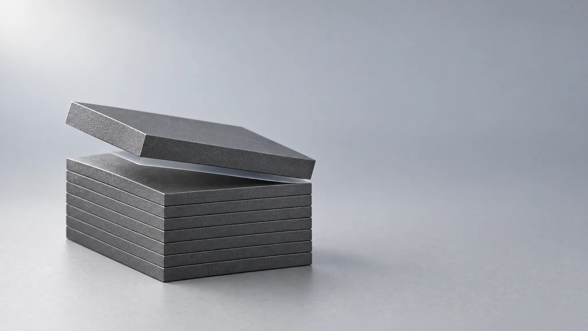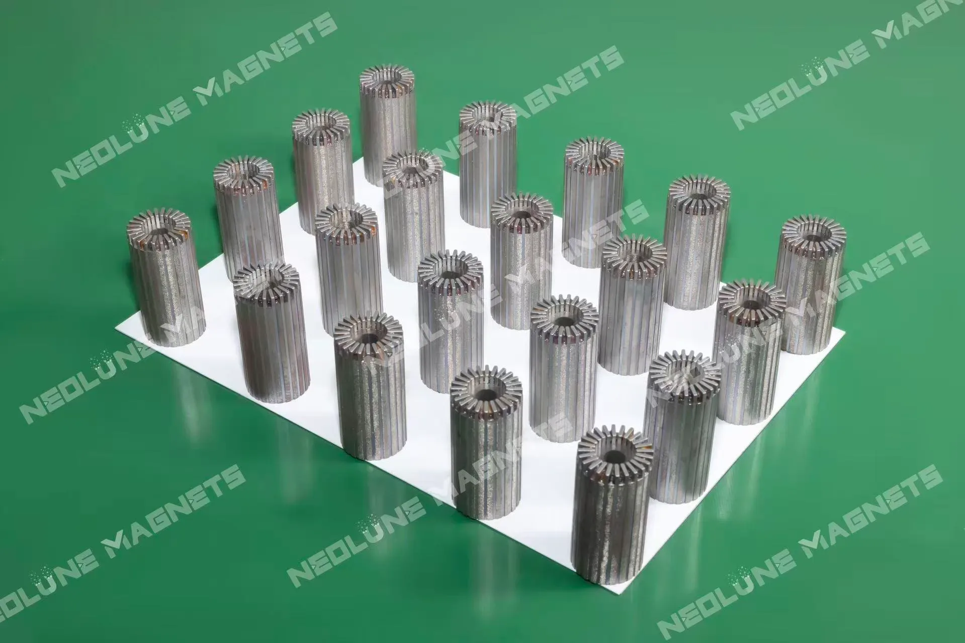
A magnet rotor drawing can be met part by part and still give a batch that drifts across the delivery. When that happens, the adhesive is blamed first. In our experience the spread is mostly decided earlier — in the magnets that were allowed into the build, and in where the fixture put them — and the steps after that decide whether the batch keeps what those two steps fixed.
Why does a magnet rotor batch drift when every part is in tolerance?
Two spreads stack, and the finished part shows only their sum.
The first belongs to the magnets. A grade on a drawing is a window, not a single value, so the pieces that arrive for one pole layout are not magnetically identical to one another. The second belongs to placement: the same magnet sitting a little further out, or turned a degree further, reads differently across the working gap. Measure the finished rotor and you get both at once — which is why a report showing one unit in the middle of its tolerance says nothing about the twentieth.
We deal with it by holding down both spreads, and by doing it early. Across a batch we hold the air-gap flux variation with the assembly fixture and with sorting of the magnet material; those are the two controls we rely on, and neither of them is the final inspection. Everything downstream then has to preserve what they established — a cure that lets a segment walk gives back part of what the fixture bought.
Which comes first, sorting or bonding?
Sorting, and it is a selection step rather than a visual pick. Our route runs machining, sorting, positioning, bonding, then curing, and the order is not administrative: a sorted set is what a fixture can place consistently, and a fixture is only as good as the set it is loading.
Sorting selects and groups the magnets for the pole layout they are going into and for the assembly conditions agreed for the order. The output is not a bin of magnets that happen to be in specification; it is a set chosen for one layout. That distinction is the whole argument. A ring built from one sorted set has a chance of repeating; a ring built from whatever the bin offered does not.
What does the fixture have to hold, and for how long?
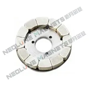
Position, orientation and spacing — and it has to hold all three until the adhesive has cured, not until the parts stop moving under a hand.
That last point is where most of the tooling effort goes. Magnetised segments push each other sideways while the joint is still soft, and a magnet that slides a fraction of a millimetre during cure is a part that can pass a dimensional check and still fail a field reading. Radial Magnets' bonding and mounting guide describes the related failure as the starved joint: magnetic attraction pulls a magnet down until the adhesive is squeezed out of the joint and the film left is too thin to carry load. A fixture that sets the gap, instead of letting attraction set it, is the same fixture that holds position while the adhesive sets.
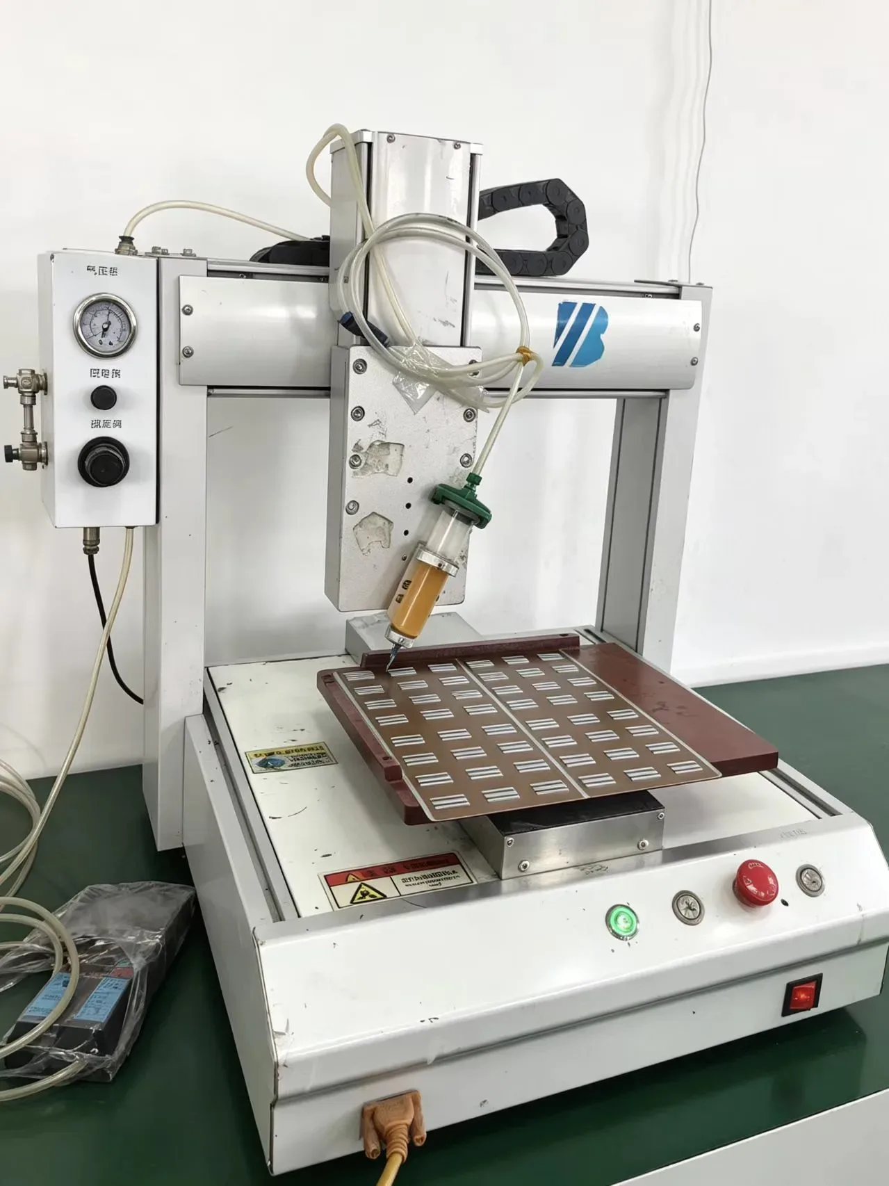
For the arrays we build, the answer is an assembly fixture with hard locating features: the segment sits where the drawing puts the pole, and the adhesive goes into that arrangement rather than the position being trusted to hands. Quantity belongs to the same argument — adhesive applied by machine at a repeatable amount is what makes the two-hundredth joint the same as the second.
Does the rotor get magnetised before or after bonding?
Whichever the magnetising equipment allows — that is the real constraint, not a preference for one route.
Bonding first and magnetising afterwards suits a closed ring component. With no magnetised parts in the build there is no repulsion to fight, and the part goes into the magnetiser as one assembly. The limit is physical: the assembly has to fit the working envelope of the magnetising equipment, so a large diameter can fall outside it however much the process would prefer that order.
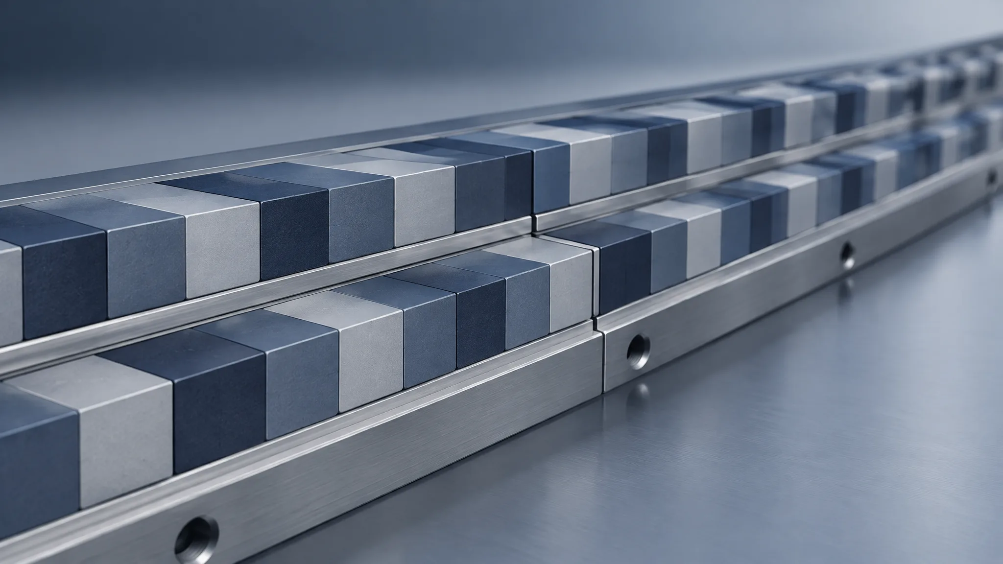
Magnetising first and bonding afterwards is what we use for large components and for linear tracks. There the segments arrive already magnetised, and the fixture has to hold them at their positions against their own repulsion until the adhesive cures — a stricter tooling problem, and the reason the same drawing at two sizes can be built in two different orders.
The useful part for a buyer is knowing which of the two applies, because it moves where the assembly risk sits. A drawing that calls for a magnetised component without saying at which stage the magnetising happens leaves that question open, and it is usually cheaper to answer it in the review than in the first batch.
Which adhesive, and what does it have to survive?
On the ring and parallel arrays we build we use a UV-cured adhesive and an anaerobic one: the first sets where the joint can be reached, the second in the confined gap between close-fitting surfaces, and the pair is used for assembly efficiency and bond reliability on those layouts.
What the joint has to survive comes from the application rather than from an adhesive's headline strength — the temperature the part reaches in service, the load path through the joint, and what the coating does at the interface. Selection belongs in the drawing review for that reason: it is settled with the magnet grade, shape and coating against the operating conditions, before tooling is cut.
Which readings can still change a batch, and which only report it?
A check earns its place while an action is still available after it. On our route the readings that meet that test are:
- At machining — dimensions on an optical measuring machine, before coating and before anything is bonded. A pocket or a carrier face that is wrong at this point is still a machining problem.
- At sorting — the point where a delivery becomes a set chosen for one layout, while the magnets can still be arranged differently.
- On the finished component — magnetic moment, and surface field with a gauss meter. On a motor part the field reading that decides acceptance is the one across the working gap: a three-dimensional scan returning air-gap flux density, how close the waveform comes to a sine, and its harmonic content.
Everything in that list is a candidate, not a fixed plan. Which checks run, on how many parts, how often, and what reaches the report are agreed per order, together with the acceptance limits and the measurement conditions. That agreement is what our inspection scope discussion is for, and it is worth settling before the tooling is cut rather than after. A delivery that arrives with a dimensional reading and a field scan can be compared with the next one; a pass stamp cannot.
What should be in the enquiry, so the batch repeats?
Five things, which are the same five our review starts from: the component type with the drawing revision; the mating interfaces and the available envelope; the pole layout and working air gap; the temperature and motion conditions; and the acceptance scope with the quantity. Surface-mounted rotor assemblies are one of the four motor structures we build this way, alongside stator and rotor pairs, linear tracks and radial permanent-magnet bearings; the same assembly question shows up wherever a magnetised rotor is sized across a gap, as it is in magnetic couplings.
Then three questions worth putting to any supplier, ours included: where the magnets are sorted, and against which conditions; what the fixture locates, and how long it holds before the part may move; and which of the checks above run on how many parts. The answers say more about whether a batch will repeat than any description of the equipment.
Timing follows the tooling. A paid sample can start from one set; a mature drawing typically samples in 5–8 working days, a new design with simulation and tooling in 7–15, and production typically runs 15–30, depending on quantity. The clock starts after the drawing is confirmed and the sample payment is received, so the revision you send is the revision the timing belongs to.
If you are holding a rotor drawing and a first batch that did not repeat, send both to our enquiry desk — the sorting step and the fixture are the first two things we will ask about.
Our engineering route is where sorting, positioning, bonding and curing are set out step by step for a project.