Eddy Current Losses in Permanent Magnets: Where the Loop Closes and What a Cut Interrupts
Why a cut interrupts only the loops whose plane it crosses, and why the faces it leaves need the drawing and the batch check to keep them apart.
How many segments, which way the cuts run, what the insulation and the coating each do, and where a segmented stack is checked before it ships.
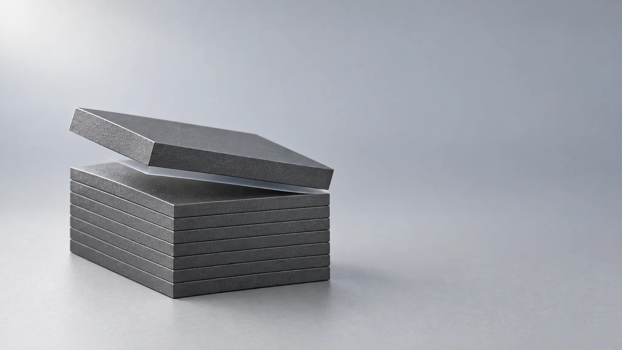
Articles in this topic ↓A laminated magnet is a magnet with joints inside it: an arc, block or sector cut into slices, insulated between the cuts, bonded back into one part and closed under an overall epoxy coating. The joints are the whole point, and they are also the whole risk. Magnet segmentation is usually argued on the loss side — how much heat a solid magnet will make at speed — and that argument settles whether to segment at all. It does not settle the part. The direction of the cuts, the slice thickness, what sits between the slices and what covers the outside are four decisions that meet on one drawing, and the last two are where a stack quietly fails to deliver the loss it was specified for.
We cut and rebuild these stacks from arc, block and sector forms, and we can deliver the stack bonded into a Halbach assembly as a single finished part — the laminated forms we build to a drawing leave as components, not as loose slices in a box. That is why everything below starts from the drawing rather than from a datasheet.
Inside the magnet. Sintered NdFeB is a conductive metal alloy, and the alternating flux a rotor sees — from the stator's teeth as the rotor passes them, from the switching ripple an inverter puts into the windings — induces current loops in the magnet body itself. Topmag's 2026 explainer on where the loop closes sets out that mechanism, and the point that matters for a drawing is simple: the loop needs a closed conductive path through your magnet. A cut is worth its cost only where it crosses that path.
How much the first cuts buy is well documented, and worth having in hand before anyone argues about money. The same page tabulates segments per pole against relative loss, with one segment at 100%: two segments at roughly 30–40%, four at 10–25%, eight or more below 10%. It labels the table as engineering reference, for a good reason. It describes the shape of the curve — the second cut buys far less than the first — not the number of cuts your motor needs.
Where the next slice costs more flux, yield and assembly time than the heat it removes. Two mechanisms set that point, and neither of them is on the drawing yet.
Loss falls with the square of the slice thickness. Ganzhou Magnets' 2026 account of the lamination process halves the thickness and gets about a quarter of the loss, then adds the practical brake: the adhesive layer has a minimum achievable thickness, and the stack still has to carry its load. The same account prices the trade the other way — the adhesive takes volume, so a laminated stack carries 2–5% less magnetic flux than a solid magnet of the same outer dimensions.
That is the argument for deciding the count in simulation rather than from a table. We review the magnetic circuit and assess array layout, segmentation and magnetisation angles against the field target in the drawing review and magnetic simulation we run on a new design. What comes back is one proposal — a segment count, a direction and a grade that the simulation supports against the field target — not three separate numbers for you to reconcile.
One check belongs in that conversation rather than in the simulation. Topmag's own FAQ says what happens when an inter-segment layer fails: the segments become one conductor again and the large loop returns. Segmentation you cannot verify is segmentation you have not bought — which turns the insulation into an acceptance item, and the next two sections are about where it lives.
The direction is a drawing decision, made against the magnetic axis rather than against the outer shape. The usual families are circumferential cuts, axial slices and the two combined; Ganzhou Magnets states the rule for a drawing as cuts parallel to the direction of magnetic flux. Read the two together and the practical test is plain: picture the loop the flux would drive inside the solid part, and check that the cut plane crosses it. A stack sliced along the loop's own plane leaves the current its path and gives up most of what it was for.
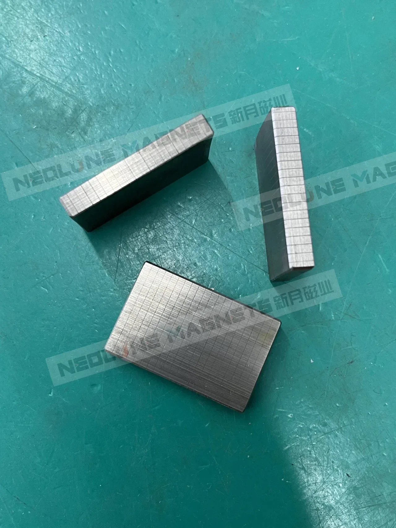
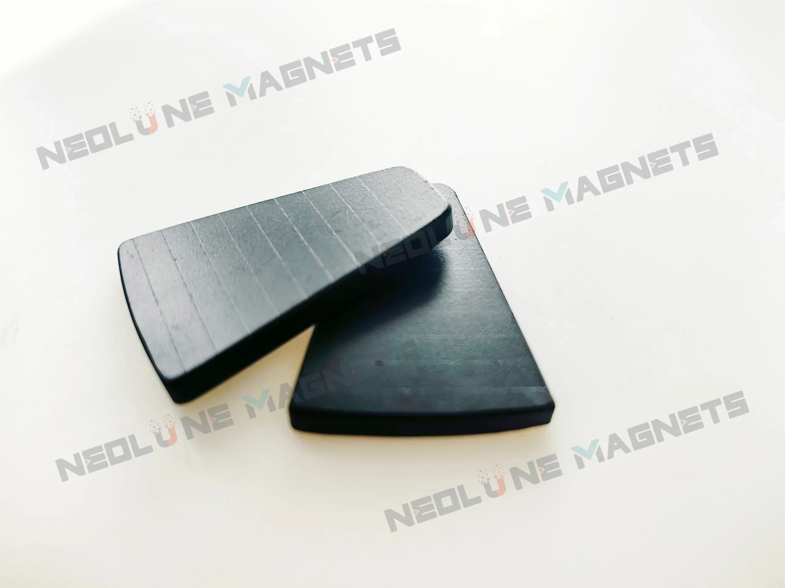
Our own forms are arc, block and sector, and segmentation follows the drawing: finished shape and envelope, segment thickness, segmentation direction and stack dimensions are asked for together, because changing one moves the others. The layer doing the electrical job is thin by design — the same Ganzhou guide puts the insulation between slices at 20–40 µm, which is their figure for their build rather than a standard we quote. That layer is specified for the motor, and what we build is checked against the requirements agreed for that component.
The order of operations then decides whether the insulation survives. A stack that is bonded and afterwards brought to its finished dimension gets one more chance to lose it: if the finishing operation smears conductive material across the joints, the layers are electrically one piece again — the risk Ganzhou Magnets flags for grinding. Finishing before bonding, or controlling what finishing does to the joint, belongs in the same conversation as the segment count.
The insulation between the segments does the electrical work. The overall epoxy coating does the surface. We keep the two separate for exactly that reason: inter-segment insulation interrupts the eddy-current path, and the epoxy coating protects the finished component.
The mistake to avoid is a conductive coating over the whole stack. Ganzhou Magnets warns that nickel and copper are highly conductive, so a nickel-copper-nickel finish on a laminated part can create a skin that bridges the layers and reintroduces the path the cuts removed; a non-conductive finish is what they recommend for the outside. Where the environment asks for nickel-copper-nickel anyway, the acceptance question has to be asked out loud: what proves the planes are still isolated after coating?
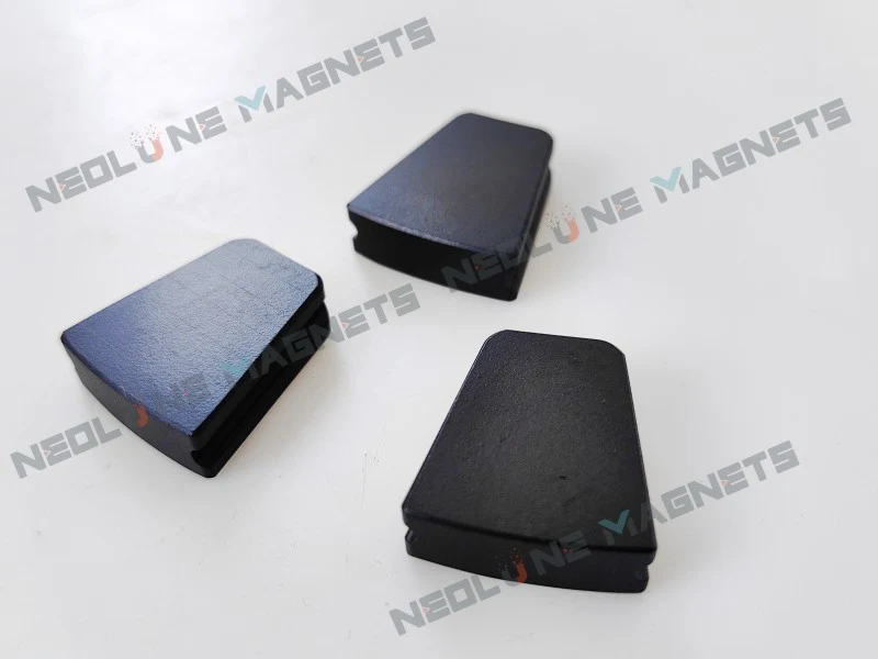
How much coating is enough depends on what it has to resist. Our usual nickel-copper-nickel runs 48–72 hours in salt spray and epoxy 200 hours and more, but without the test standard and conditions those hours are a direction, not an acceptance criterion — the coating checks agreed for an order are where they become one.
The items are agreed per order. For a stack the ones that matter are dimensions, magnetic field and flux, and coating, plus the temperature-demagnetisation check where the operating conditions call for it. We can supply batch dimensional, magnetic field and coating reports; which items run, how often, and what the acceptance limits are, are set for the order instead of by one fixed inspection plan.
If the stack runs hot and at speed, add the bonding to that list. The shear strength of the adhesive at the operating temperature, and what a cold-to-hot cycle does to the joint, are the questions that decide whether a stack delaminates before it demagnetises. Put them into the acceptance items with their test conditions when the application warrants it, because a bond figure quoted at room temperature says little about a rotor at its working temperature.
One distinction matters most to a buyer of a laminated part. A three-dimensional field scan — the one that reads back air-gap flux density, the shape of the waveform and its harmonic content — needs a finished part to scan. On a stack that has not yet become an array, the evidence you can agree is dimensional, flux, coating and insulation; the field map belongs to the assembly the stack goes into.
If insulation is what you are paying for, say so in the acceptance items. Ganzhou Magnets describes the check a buyer can ask for: an LCR meter or impedance analyser across the lamination planes, with a properly insulated stack reading in the mega-ohm range and a failed or smeared layer reading in the milli-ohm range. Whether that check runs on every batch is an agreement for the order, like every other item here.
Yes. The stack can be bonded into a Halbach array and delivered as one finished part, which is the arrangement behind the Halbach assemblies we build — ring bores from φ10 to 400 mm, linear sections of 10 to 600 mm that can be joined into longer travel, magnets no thinner than 2 mm, all of it subject to the drawing and to the acceptance conditions agreed for the order.
For lamination, we insulate each magnet slice before stacking and pressing the slices together. For magnet assembly, our usual route is to magnetise the magnets first, then position and bond them using dedicated fixtures. The assembly sequence and tooling constraints are confirmed during project drawing review; any alternative route requires confirmation for the specific structure and requirements.
Five inputs, in the order that lets us quote instead of guess:
Timing follows the drawing. A mature drawing typically samples in 5–8 working days; a new design with simulation and tooling in 7–15; production typically runs 15–30, with the clock starting after the drawing is confirmed and the sample payment is received. A prototype can start from one set.
Send the finished shape, the segment thickness, the insulation requirement and the motor conditions together, and the answer comes back as one proposal — count, direction, layer, coating and checks — rather than as a catalogue line. Send the drawing with those conditions and the review starts where the loss argument ended.
Why a cut interrupts only the loops whose plane it crosses, and why the faces it leaves need the drawing and the batch check to keep them apart.