Where do eddy current losses in permanent magnets come from?
Eddy current losses in permanent magnets are made inside the magnet, and that is the part to hold on to. Sintered NdFeB is a metal alloy rather than a ceramic, so a changing flux that passes through the body drives a current through the magnet itself, and the material's own resistance turns that current into heat.
Two fields do the driving, and neither is the field that produces torque. One is the change in permeance as the rotor passes each stator tooth and slot, which ripples the air-gap flux at slot frequency. The other is the switching ripple an inverter puts into the windings, which reaches the rotor as an asynchronous field at switching frequency. Both alternate far faster than the shaft turns.
What follows for a drawing is geometric. A current needs a closed path, and the energy it converts is charged against the area that path encloses. A solid magnet offers the largest path its own outline allows — which is why, at the same speed, a bigger piece of the same material is worse than a smaller one.
So the question is not whether your rotor has eddy currents. It is which loops your geometry closes, and which of them you are prepared to pay to interrupt. The loss side of that argument belongs to simulation on the complete motor. What follows here is the other half: what a cut physically does, and what the operations around it decide.
What does one cut interrupt?
Only the loops whose plane it crosses. A cut taken across the path a current would travel interrupts it; a cut that runs in the plane of that path leaves the current a route very nearly as good as before — cost paid, benefit not collected.
That is why direction is a drawing decision rather than a machining preference. The test that holds is to picture the loop the changing flux would drive inside the solid part. The flux threads the loop, so the loop closes around the flux in the plane normal to it, out to whatever edge lets it complete; the cut is worth making where its plane crosses that circuit rather than running alongside it. Circumferential cuts, axial slices and the two combined all answer that test in different places. The three families are a vocabulary, not a recommendation.
A cut also leaves something behind. It is not a wall of no thickness: it is two faces with a layer between them that keeps them electrically apart, and that layer is what the rest of the route is working on.
And it costs. The kerf takes material with it, and the layer is not magnetic, so a stack is not the magnet it was cut from: it fills the same envelope with slightly less magnet inside. Two costs, both real — which is why a cut has to cross something worth crossing.
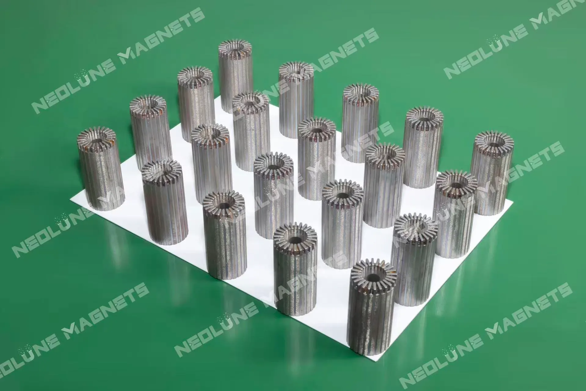
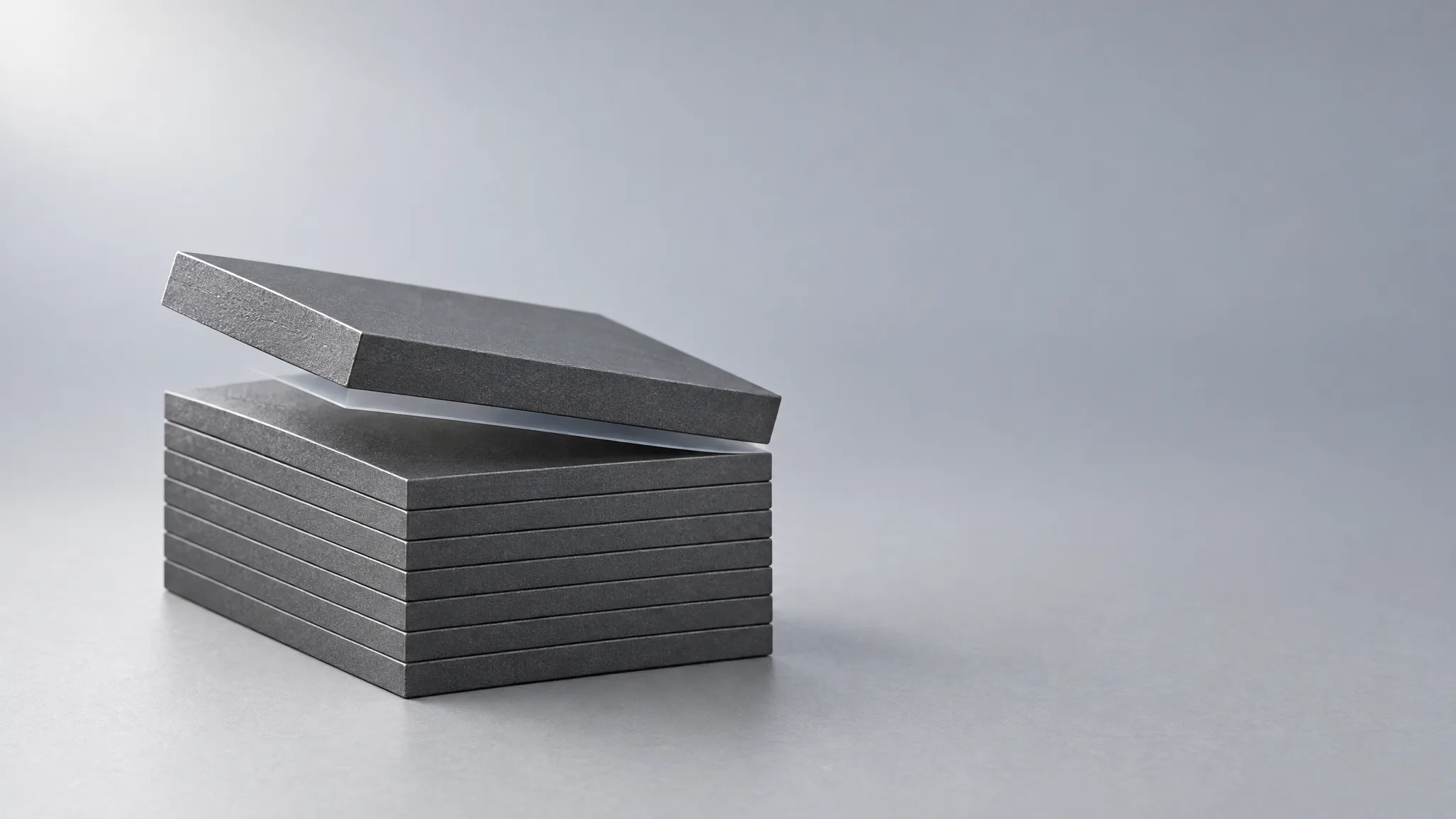
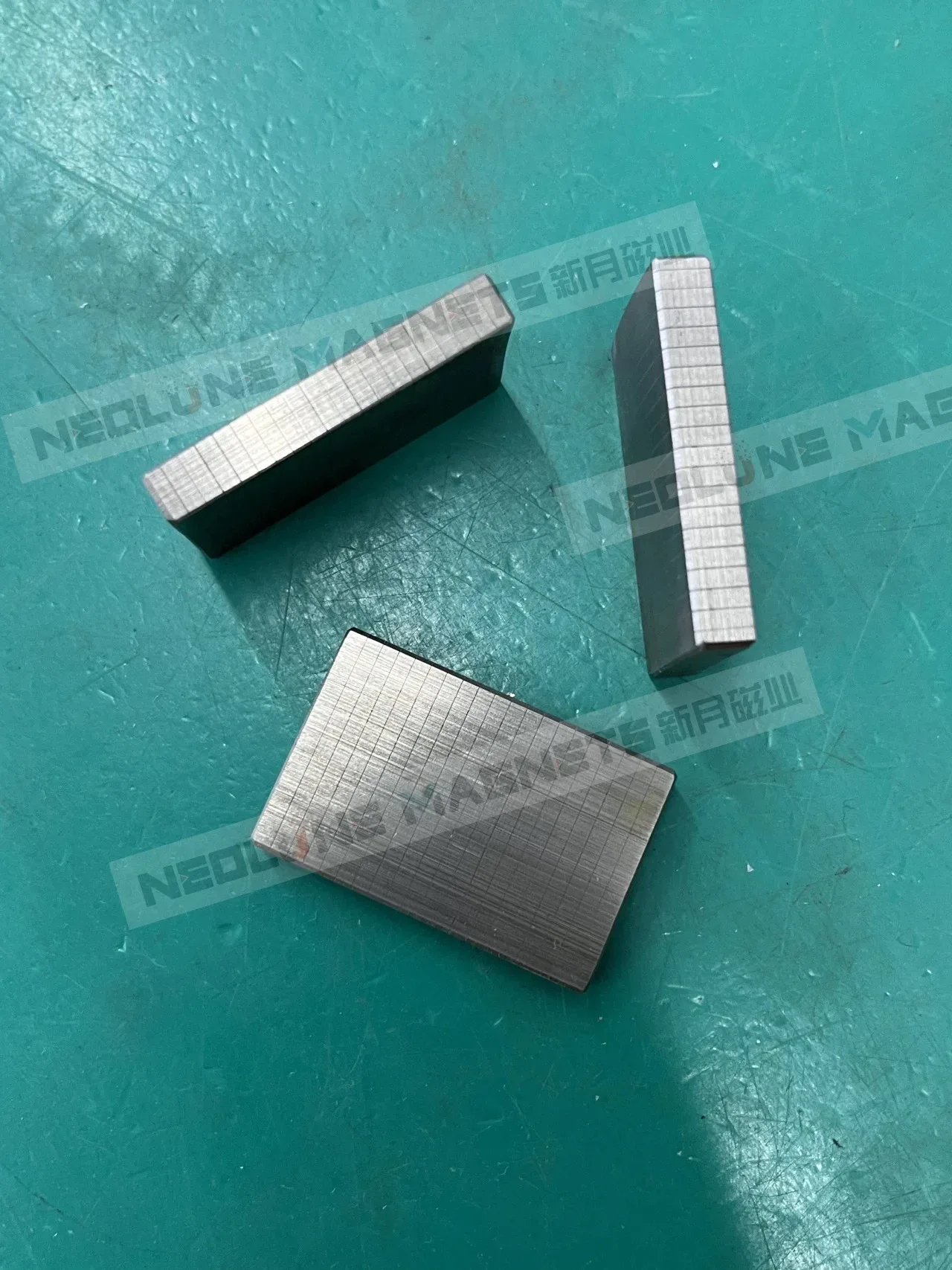
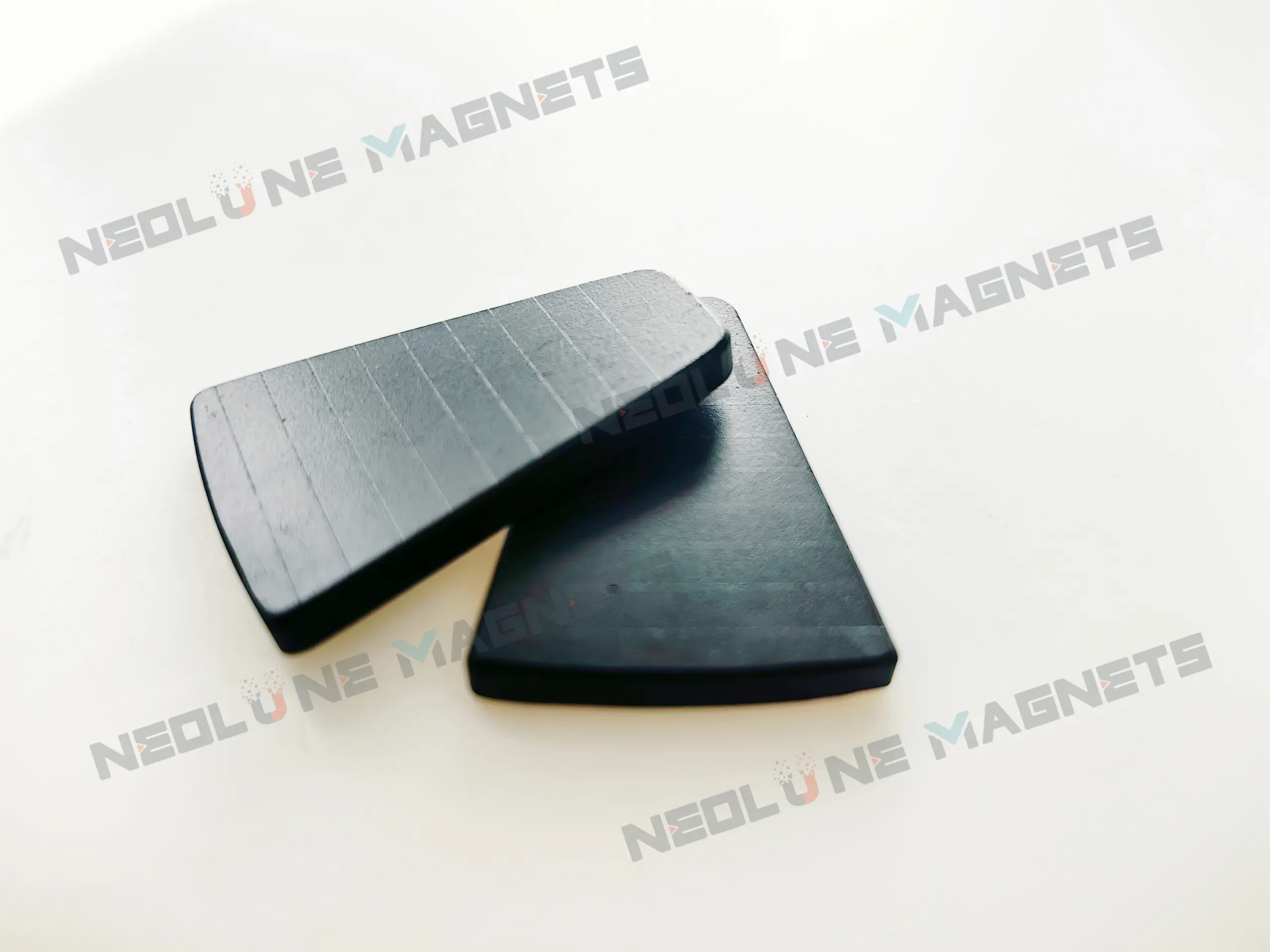
We cut arc, block and sector forms into slices, insulate between them and bond the stack back into a single part under an overall epoxy coating; the shapes and the split follow the drawing — the laminated forms we build to a drawing.
Which steps after the cut can close the path again?
Any step that touches those two faces, and a magnet route touches them several times. Our magnet route runs from the blank into machining — slicing, profile grinding, wire sawing, double-side grinding — then surface treatment (chamfering, barrel plating, cleaning), then assembly and inspection. A laminated form adds two steps of its own: the insulation and bonding between the slices, and the overall epoxy coating over the finished part.
Read the route as a series of chances to leave the joint as it was, and four of them matter more than the rest.
A conductive finish on a cut face. Nickel and copper are metals; plated onto a cut face they conduct as the magnet does. Plate the slices loose and every cut face arrives at the joint already covered in metal, so the insulation between them is the only thing standing between two conductors. Ganzhou Magnets makes the same point about a nickel-copper-nickel finish over a finished stack in its 2026 guide to laminated NdFeB magnets: a conductive skin around the whole part bridges the layers and hands back the path the cuts removed. Epoxy, which is what closes our stacks, does not.
Metal carried across the joint by a finishing pass. Grinding or chamfering after the stack is bonded can move material across a layer that is thin by design. It is the same failure as plating, arrived at from outside instead of underneath.
Residue on a face. Cleaning sits in the route for a reason: whatever is on the face when the adhesive goes down is what the bond holds.
A chamfer. A chamfer is a bevel, and a bevel is where a coating has to turn a corner. Where a drawing puts one at a cut edge, the cross-section at that corner is worth asking for by name.
What can a batch check see at a joint?
Less than the question deserves, unless the joint is written into the order. Our five standard check items are dimensions and mechanical fit, appearance, magnetic properties (remanence, coercivity, magnetic moment, hysteresis, deviation angle, weight loss), coating corrosion resistance, and magnetisation and packaging. Not one of them is an electrical check across the layers of a stack.
So a stack can pass all five and still have nobody check whether its layers are separate. What the checks do give you is a set of instruments that sit close to the joint:
- After machining: dimension on an OMM, plus roughness.
- After surface treatment: coating thickness by X-ray, a metallographic cross-section through the magnet and its coating, and SEM-EDS analysis of what the layer is made of.
- On the finished component: magnetic moment and surface flux.
An X-ray thickness reading is a number at a point. A metallographic cross-section shows the layer where it has to meet the edge — a joint, a bevel, the geometry a thickness figure cannot describe. SEM-EDS answers a different question again: not how thick, but what is there.
If insulation is what you are buying, make it an acceptance item and give it a method, a temperature and a coverage. How the checks for an order are agreed — items, criteria, coverage and frequency — is a conversation to have before production, not a clause to argue after it.
What has to be on the drawing for the cut to survive?
Five inputs, in the order that lets a supplier answer instead of guess:
- The finished shape and the assembly envelope: the arc, block or sector drawing.
- The lamination: segment thickness, segmentation direction and stack dimensions.
- The insulation and bonding: what the layer between segments has to do at the operating temperature, and how it will be accepted.
- The coating: the overall epoxy specification and the environment it has to meet.
- The motor conditions: working temperature, speed and the magnetic-circuit requirement the stack serves, with the quantity.
Three more questions belong in the same pass, because they move the joint between operations rather than changing a number: whether the outside finish is epoxy or a metal coating; whether the chamfer is cut on each slice or on the bonded stack; and whether the final dimensions come from machining before bonding or after it. Each answer changes what can close the path again, and the joint is the part that has to survive.
Where does the loss argument end?
In simulation, on the complete motor — which is where a table of generic loss reductions stops being useful. The same cut removes heat in one machine and takes flux without a return in another, and that difference only shows in the magnetic and thermal model of the whole design.
What we do instead is review the magnetic circuit and assess the array layout, the segmentation and the magnetisation angles against your field target in drawing review and magnetic simulation, and answer with one proposal rather than three numbers for you to reconcile.
Timing follows the drawing. A mature drawing typically samples in 5–8 working days, a new design with simulation and tooling in 7–15, and production typically 15–30 — the clock starting after the drawing is confirmed and the sample payment is received. A prototype can start from one set.
Send the drawing with the finished shape, the segment thickness, the insulation requirement and the motor conditions, and the review starts where the loss argument ended.