Magnet Rotor Assembly: Sorting, Positioning and What Holds a Batch Together
Where a magnet rotor's batch spread comes from: sorting magnets for the layout, locating them in a fixture, and choosing the magnetising order by part size.
Surface-mounted permanent magnet rotors, stator and rotor pairs, linear tracks and radial PM bearings, grouped by installation interface and what proves a batch.
Articles in this topic ↓A motor magnetic component is chosen by the interface it installs into, not by the grade of the magnet inside it. An engineer who opens a drawing review with "N42 or N48" has usually skipped the decision that decides what the part has to survive. Depending on the axis, the answer is one of four structures, each with its own obligations: a surface-mounted permanent magnet rotor that lands on your shaft, a stator-and-rotor pair that has to hold a working air gap with parts we do not make, a linear magnet track that mounts to a carriage, and a radial permanent-magnet bearing set that runs inside a bore. Each one asks for different lines on the drawing, and each is proved by a different measurement at the end of the batch.
We build all four as finished assemblies, which is why our reviews start at the interface and work back to the magnet rather than the other way round.
The structure is the first thing to name, because it decides what the drawing has to locate.
| Structure | What arrives | What the drawing has to locate |
|---|---|---|
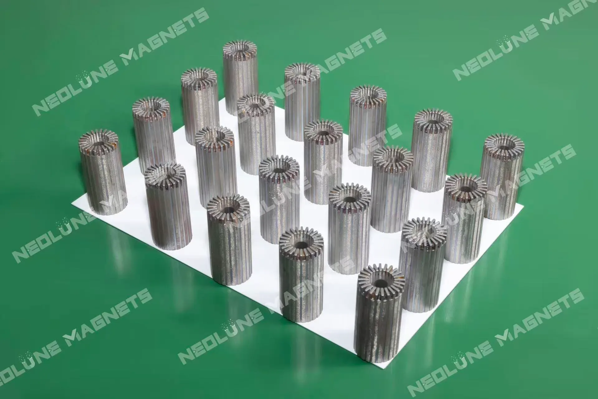
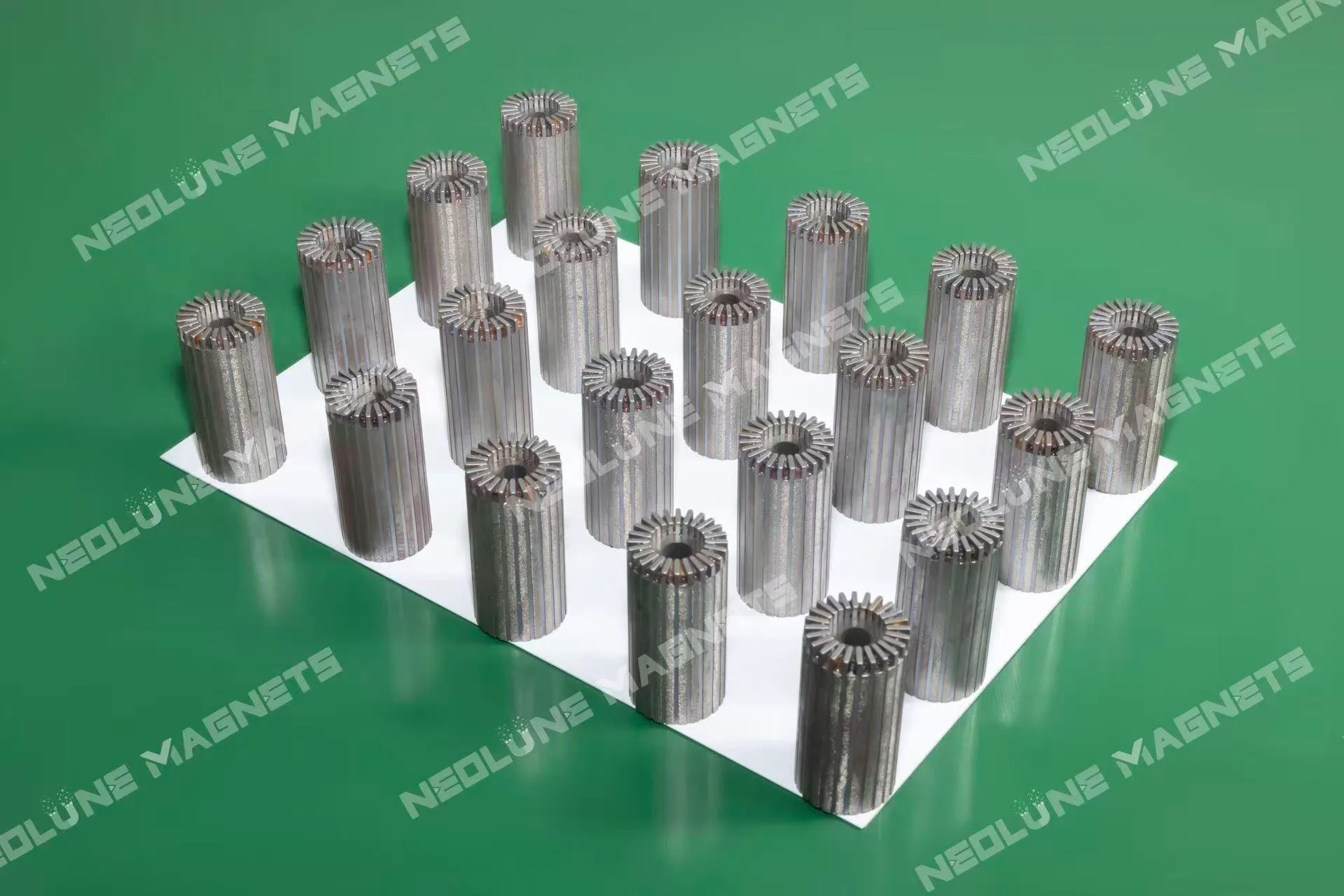
| Surface-mounted rotor assembly | Magnets arranged around the perimeter of a rotor body, with a central bore | Shaft and bore fit, the magnet envelope, pole layout, working air gap |
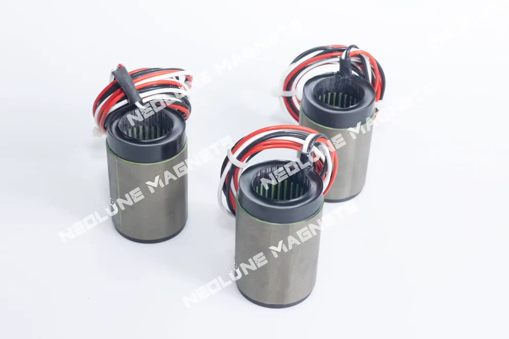
| Stator & rotor components | Stators with their leads in place, and the rotor that runs with them | Lead exit, mating faces, the gap that closes between the two parts |
| Linear motor magnet track | A magnet row carried in a channel section | Section and mounting face, the travel the track has to serve |
| Inner-rotor (radial) permanent-magnet bearing | Ring assemblies that run inside a bore | Bore and ring fits, orientation of the segments |
The right-hand column is the actual work. When a drawing arrives without it, the first review is spent finding it out. The shapes in the left-hand column are the four groups on our motor components page, and the reason they are grouped this way is that each one has its own installation inputs rather than its own magnet.
Two of them are shaped by the machine they sit in. Stator components arrive with their leads already brought out, so the drawing has to say where they leave the part — a lead that exits in the wrong place is a harness problem at assembly. A linear track carries its magnets in a channel section, so the section becomes a mounting feature: the face that bolts to the carriage is part of the part, not an accessory.
Three things: the shaft, the magnet envelope, and the protection of the magnet's outer surface in service. The third carries most of the mechanical argument.
Sintered NdFeB and SmCo are weak in tension, so at higher speeds the usual retention is a sleeve fitted with an interference that keeps the magnets in compression while rotation tries to pull them outward. Barrans and Mallin's 2018 open-access chapter on the mechanical design of SPM rotors sets out what that costs: a thicker sleeve is a larger effective air gap, which takes back part of the electromagnetic performance the magnets were bought for, and the analysis you choose — thin cylinder, plane stress, plane strain — changes the stress you predict, most of all as the sleeve thickens and the diameter shrinks.
For the component, two lines do that work and are easy to leave blank: the tolerance on the magnet's outer surface where the sleeve bears, and the bond line underneath it. The third point is not ours to decide — whether the sleeve, the shaft and the balancing stay on your rotor line or arrive with the assembly. Say which in the inquiry and the conversation is about magnets; leave it out and the conversation is about scope.
There is a second line that is often left to us by default and should not be. A surface-mounted rotor's magnets are magnetised radially, or as a circumferential multipole around the ring, and the pattern decides the fixture that holds the segments and the way the field is read back at the end. If your magnetic model assumes a pattern, put it on the drawing.
Last, and against a working point rather than against a table. Our range covers sintered NdFeB from N35 to N54 across the M, H, SH, UH and EH series, and SmCo where the duty needs it. None of those designations chooses itself. What chooses is the flux the working gap needs, the temperature the part reaches in service, the demagnetising field it meets at the worst point of the cycle, and the coating the environment asks for. The range is the envelope a conversation starts from, not a catalogue of ratings.
Simulation is where those inputs are tested against each other — the array layout, segmentation and magnetisation direction against the field target; the grade, shape and coating against temperature, component geometry and quantity. We would rather settle that there than find it in a batch report after the tooling is cut.
So when a grade is proposed, ask what working point and temperature the proposal was checked at. A temperature ceiling quoted without the grade, the working point and the duty is not a specification, and the flux that remains at your operating temperature is the number to design against.
Every check has a stage where it can still change something. After that stage it only sorts good parts from scrap, so the plan follows the process instead of sitting at the end of it.
Which of those run, on how many parts, how often, and what reaches the report is agreed per order, together with the acceptance limits and the measurement conditions — the check items and the batch report are set out here. Coverage decided after the fact is not evidence, and a report written for another project does not carry over to this one.
One figure we keep to its own class. ±0.05 mm is an assembly accuracy we quote for 3C and robot-joint components; it is not a rotor figure, and it should not be copied into a motor drawing because it appeared in a headline.
Five things make a review possible: the component type with its drawing revision; the mating interfaces and the available envelope; the magnetic layout, pole layout and working air gap; the temperature and motion conditions; and the acceptance scope with the quantity. That list is the whole of what our engineering review asks for, and it is short on purpose: everything else can be discussed once those are fixed.
Timing follows the same logic. A paid sample can start from one set; a mature drawing typically samples in 5–8 working days, a new design with simulation and tooling in 7–15, and production typically runs 15–30, depending on quantity. The clock starts when the drawing is confirmed and the sample payment is received, so the revision you send is the revision the timing belongs to.
Send it with the interface and the acceptance scope on it, and the review begins where it should — with the structure the magnets have to serve. Drawings go to our enquiry desk, and the answer comes back about the part, not about a catalogue number.
Where a magnet rotor's batch spread comes from: sorting magnets for the layout, locating them in a fixture, and choosing the magnetising order by part size.