One direction per segment
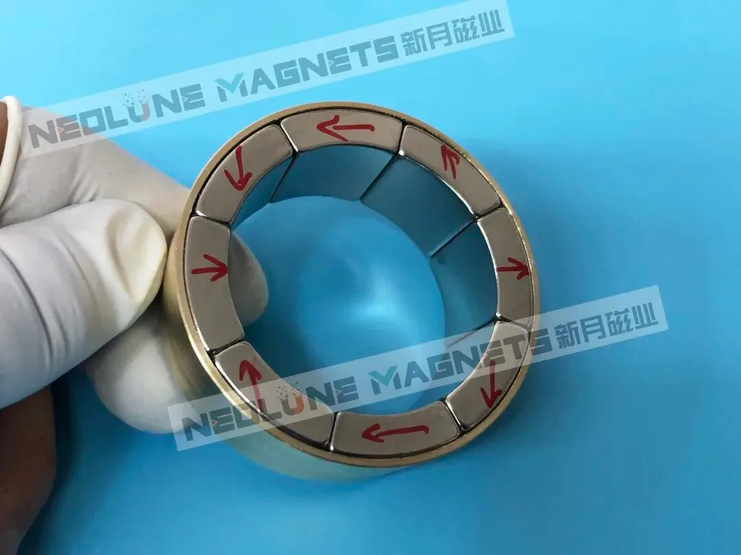
Each magnet is set in one direction, shown by its arrow. Neighbouring magnets point differently, and that rotation concentrates the field on one side of the array.
Choose the structure, the size and the segment count, and the drawing shows the magnetisation direction of every magnet and how the pattern repeats.
The drawing covers geometry and magnetisation direction. Field, loss and torque values follow from the grade, the working gap and the operating point.
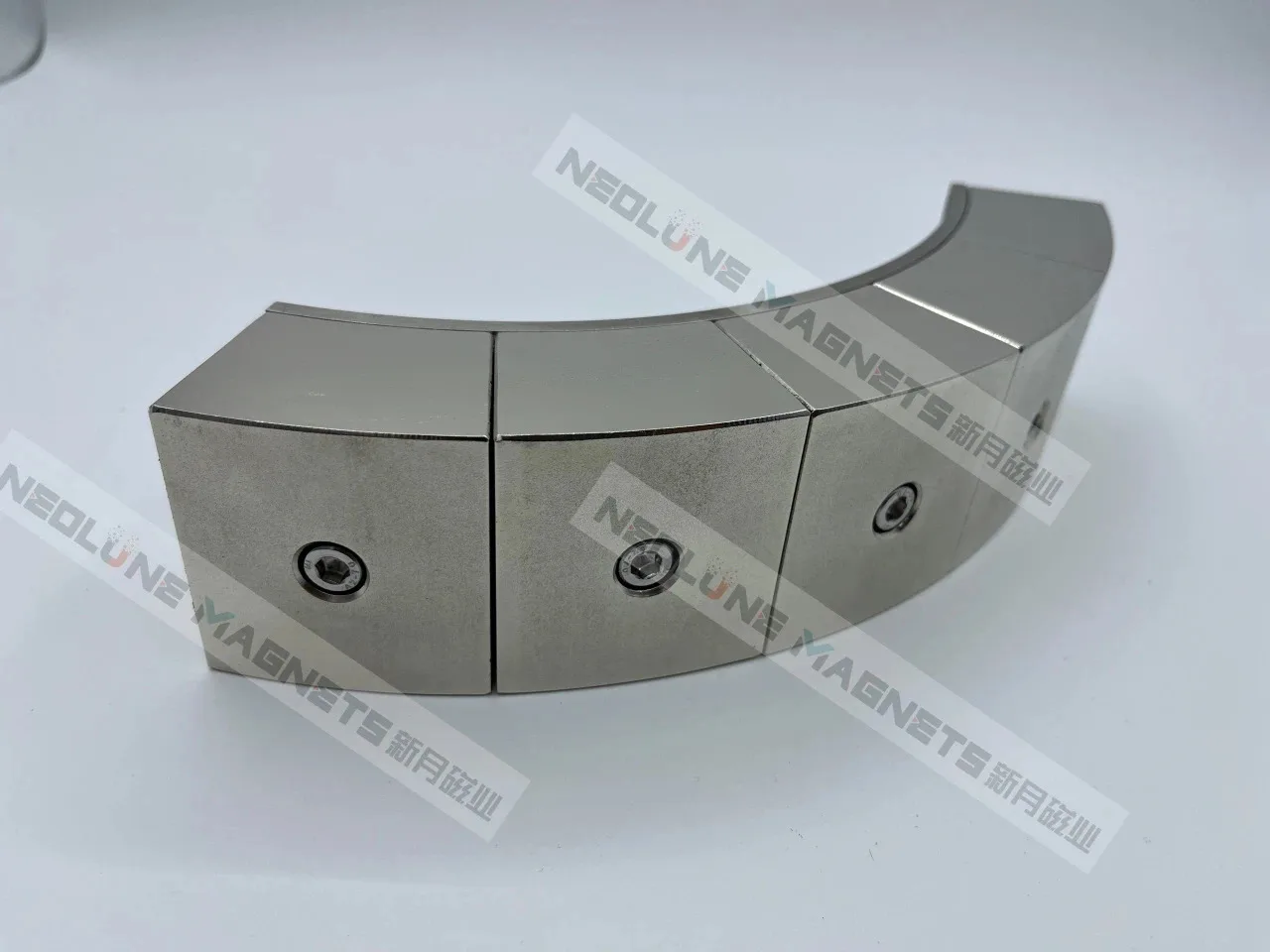
Outside the range we quote from existing production: ring bores φ10–400 mm, linear sections 10–600 mm, magnets from 2 mm. We would review the design with you.
| Structure | Ring |
|---|---|
| Bore diameter | φ60 mm |
| Section length | 120 mm |
| Magnet thickness | 6 mm |
| Pole pairs | 2 |
| Segments per pole | 4 |
| Magnetisation step | 45° |
| Segments | 16 |
Each magnet is set in one direction, shown by its arrow. Neighbouring magnets point differently, and that rotation concentrates the field on one side of the array.
At four segments per pole the direction turns 45° from one magnet to the next; at six segments per pole it turns 30°.
Segments are numbered in one direction round the ring, along a track or across an arc, starting at the first pole.
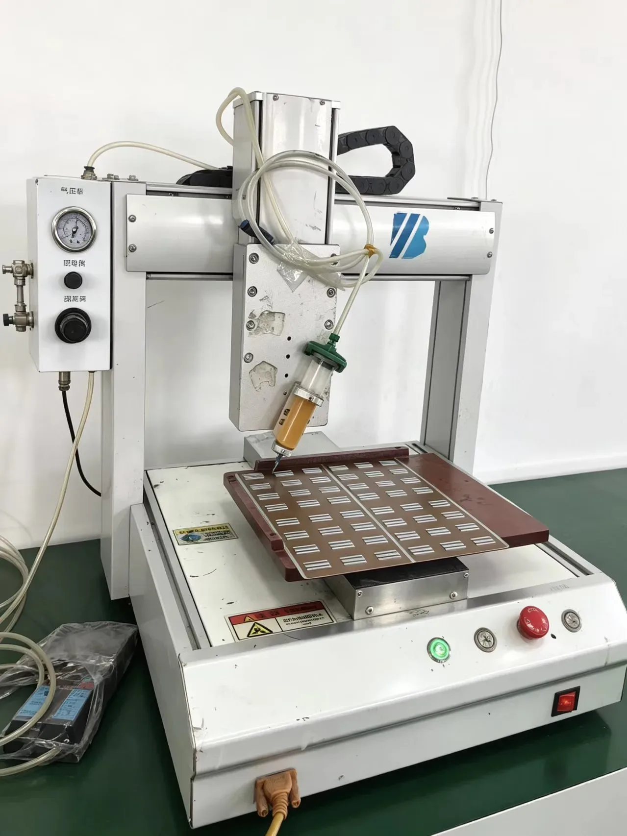
Ring, cylindrical, linear and arc forms are made with the segment count and the magnetisation angles agreed on your drawing.
Send the copied summary with your drawing, target field and operating conditions; segment count, grade and magnetisation are checked against your installation.
Submit your inquiry using the form. Email drawings to sales@neolune.com.