Every magnet specification meets the same question in the end: what does the worst case do to this magnet? A motor that stalls while hot, an actuator back-driven past its stop, two arrays that snap together on a bench. The answer can be squeezed into one figure, a demagnetization margin, and that single figure is a poor fit for the subject: magnet demagnetization arrives in three forms that cost three different things, and each form is answered by a different document.
Reversible loss is a number for the performance budget. Irreversible loss is a working-point decision that belongs on the drawing. Structural loss is a material limit no inspection recovers. Mix the three into one margin and a project buys a steeper grade than its working point needs, while the acceptance — the check that would prove the batch kept what the drawing assumed — stays unwritten.
What does magnet demagnetization actually cost you?
Three different things, and they are not three degrees of severity.
Reversible loss is a design assumption. Flux falls as the magnet warms and returns when it cools, and the size of the swing is described by reversible temperature coefficients, which differ by material class — Magma Magnetic Technologies' stability note sets them out in one table for NdFeB, SmCo, Alnico and ceramic. It is paid for in the cold-and-hot performance budget, and it is not a defect: a reading taken at temperature shows it, a reading taken at room temperature does not, which is why it is not what a demagnetization acceptance is written against.
Irreversible loss happens when the operating point drops below the knee of the demagnetization curve at that temperature. The flux does not come back on cooling; a remagnetizing field would restore it, which is the boundary Adams Magnetic Products draws between its loss categories. Magnequench adds the practical catch: once the magnet sits inside a finished component, re-magnetization is usually impossible, so what is recoverable in theory is final for that unit.
Structural loss is the material changed — metallurgical change, or oxidation where temperature and moisture meet — and no re-magnetization brings it back. Magma treats it as the third category; Magnequench calls it structural and notes that it is the loss that ends a magnet's service.
That is the argument against the single margin. It mixes a coefficient, a curve and a material limit, and only the middle one is a working-point error. A drawing that says "margin 1.5" tells a supplier nothing about which of the three it is buying, and no incoming check will tell you either.
Which loads take flux away for good, and which only bend it?
Permanence is a property of the operating point, not of the load. What heat, an opposing field or a change of circuit does to a magnet depends on where the magnet sat when the load arrived: the curve's shape at that temperature, and the permeance of the circuit around the magnet.
That is why a list of causes is less useful than it looks. The same opposing field that is harmless inside a closed yoke can be permanent loss for a magnet standing on an open face. Use a cause list to know what to compute, not to know what to conclude.
| Load | What it changes | What it costs | Where it is answered |
|---|---|---|---|
| Heat, steady state or transient | The curve sits lower and its knee moves toward the working point | Reversible first, irreversible once the point is below the knee | The performance budget, then the drawing |
| An opposing field — fault current in the winding, a second array, the magnet's own field with the working face open | Pushes the operating point down the second quadrant | Reversible, or permanent, by the same knee test | Simulation at the worst case |
| A permeance change — the magnet out of its circuit, the gap opened, a yoke taken away | Moves the load line rather than the curve | Reversible until the load line crosses the knee | The drawing, and the fixture that holds it |
| An impact, a chipped corner, a dropped rotor | Removes material, coating and part of a pole face | Not demagnetization at all | Packing and the assembly method |
| Time | Magnetic creep: the least stable domains relax, quickly at first and then slowly | Small in rare-earth grades, and continuous rather than a one-off (Magma) | The performance budget and the first acceptance reading |
Read the table down its third column: that is what the drawing has to survive. The fourth says who owns the answer, and two of these rows — the temperature at the hot spot and the permeance at the worst gap — are the machine designer's to supply, not the magnet supplier's.
Why does a knock look like demagnetization, but isn't?
Because a chipped pole face and a demagnetized sector both reduce the same surface reading, and only the part in your hand separates them. Adams is direct on the physics: shock and vibration have very little effect on today's permanent magnets, and the hazard in the same paragraph is that the materials are brittle and crack-prone.
Our shipping assumption follows the same line. Parts leave packed against chipping and with magnetic shielding, because the risk in transit is a broken corner rather than a lost field, and a finished array is not built to be taken apart on a fitting line. Inside the plant the equivalent hits look different — two magnetized assemblies meeting, a rotor dropped on a bench, a fixture that lets a segment fly into place — and each is a fixture and handling decision that is cheaper to take before the pattern and the grade are frozen. That is why we review handling in the same conversation as the magnetic design.
What belongs on the drawing, and what belongs on the order?
The drawing carries the hot working point; the order carries the acceptance that proves it. With either one missing, the grade you buy and the acceptance you get are guesses.
Four inputs belong on the drawing:
- The magnet's own temperature at its worst point — the hot spot of the magnet, not the ambient of the machine, and the transient as well as the steady state.
- The demagnetizing field at that temperature — the winding current in the fault case, the opposing array, and the magnet's own field with the working face open.
- The permeance of the real circuit at its worst gap — worst eccentricity, the adhesive, the coating, the can or sleeve over the magnet.
- A grade whose curve keeps that point above its knee at that temperature, chosen by grade rather than by series, because a series temperature rating is not a working point.
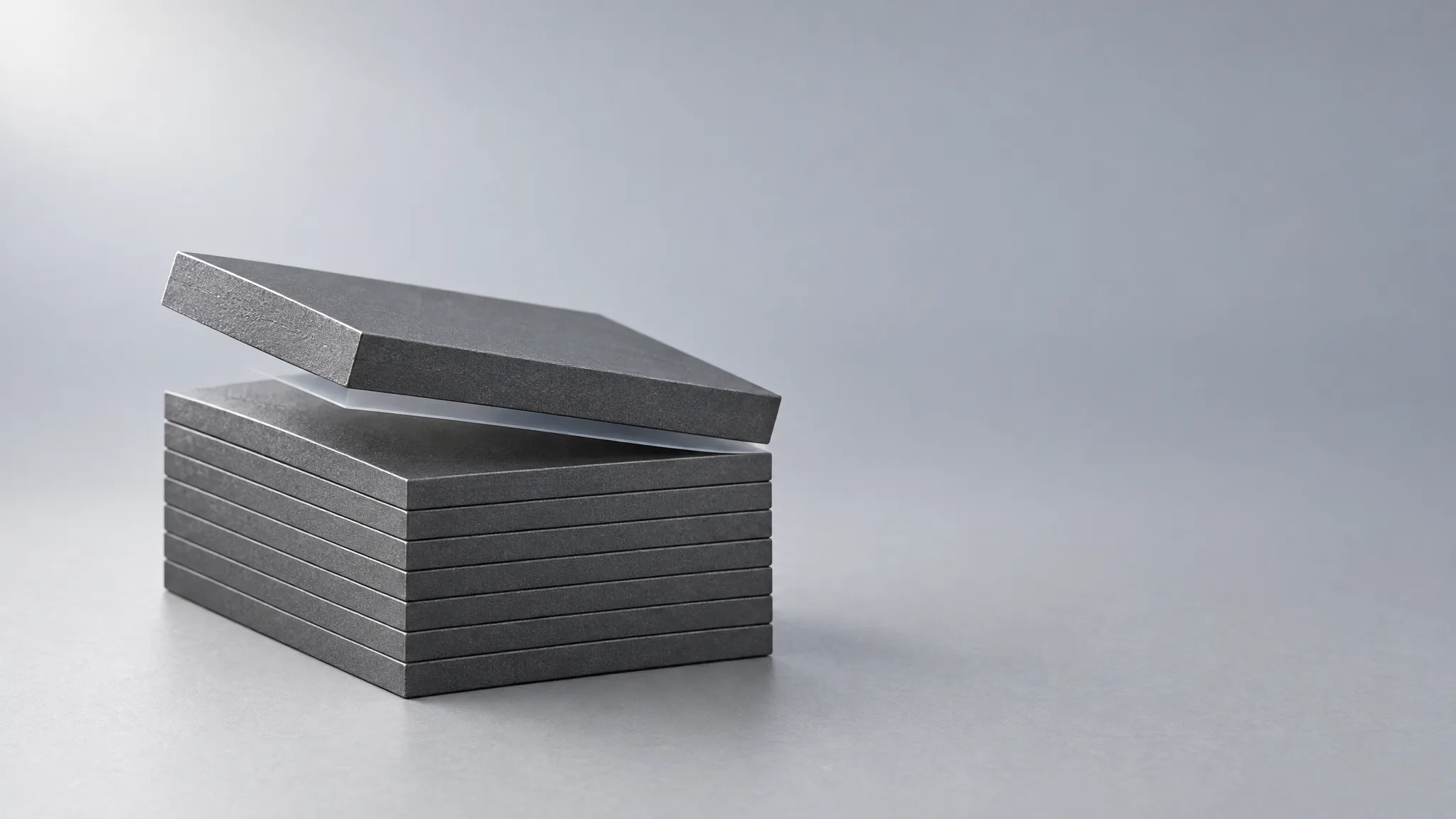
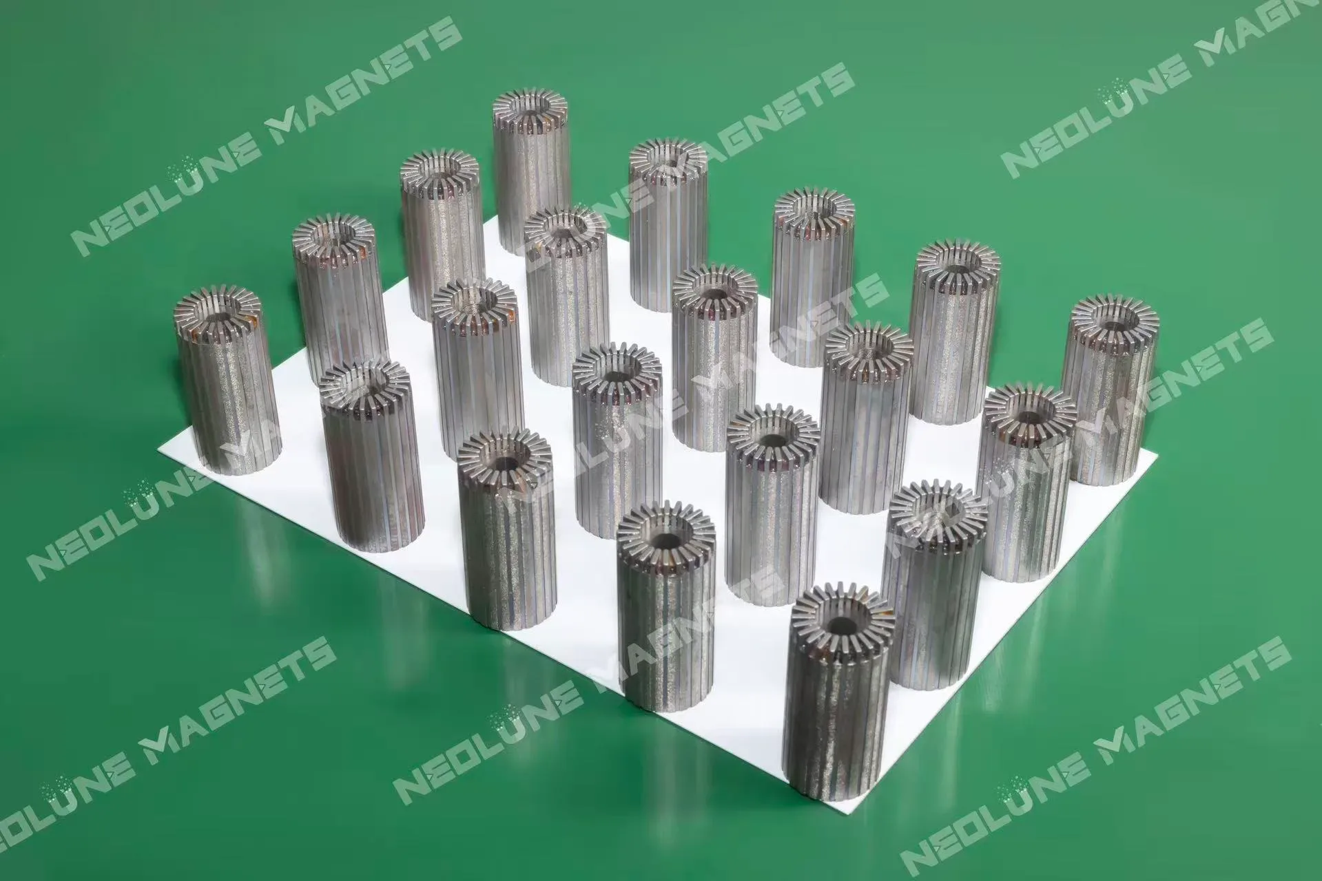
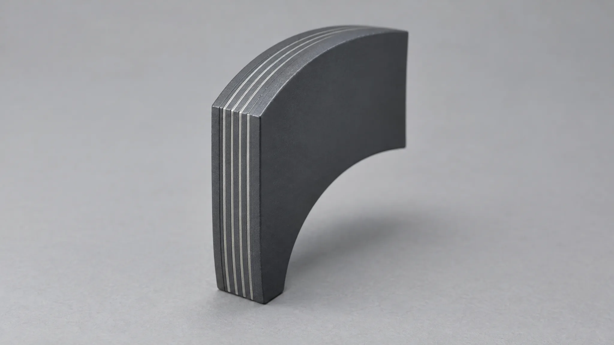
Where the magnet's own heating is a large share of the worst case, the heat path is a design item in its own right. Segmentation with insulation between the slices interrupts the eddy-current path inside the magnet, which is how a high-speed design stops the magnet's own losses from becoming its demagnetizing load — the purpose of the laminated magnets we build, in arc, block and sector form.
The order half is one sentence with three blanks in it: after the exposure we name, the field may fall by no more than this much, on this many parts, measured this way — by magnetic moment on a magnet or a segment, by the field map and readings across the working face on a multipole assembly. Leave it unwritten and "no demagnetization" stays a claim rather than an acceptance item.
How do you prove a batch kept its flux?
By measuring the finished part, with a method that repeats on the same part after the exposure. A limit needs a measurement that repeats; otherwise the check is a coin toss with a form attached.
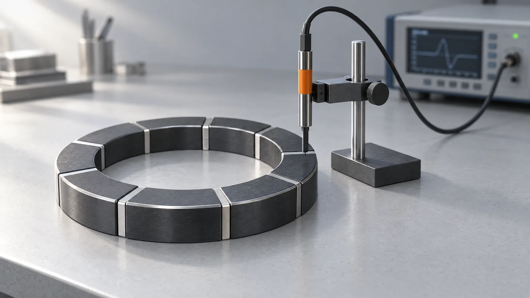
Our assembled parts are read two ways, magnetic moment and surface field, and the difference decides what each can carry. A Hall probe reads the field at a point on an open face, which is not uniform, so the number depends on the probe's plane and its distance from the pole; EPI Magnets' account of the instruments says the same and adds that thin and arc-shaped magnets read poorly at the surface altogether. Magnetic moment, taken in a Helmholtz coil, is the route that holds up across those shapes, which is why a magnet or a segment is measured by its moment and the same piece is compared before and after.
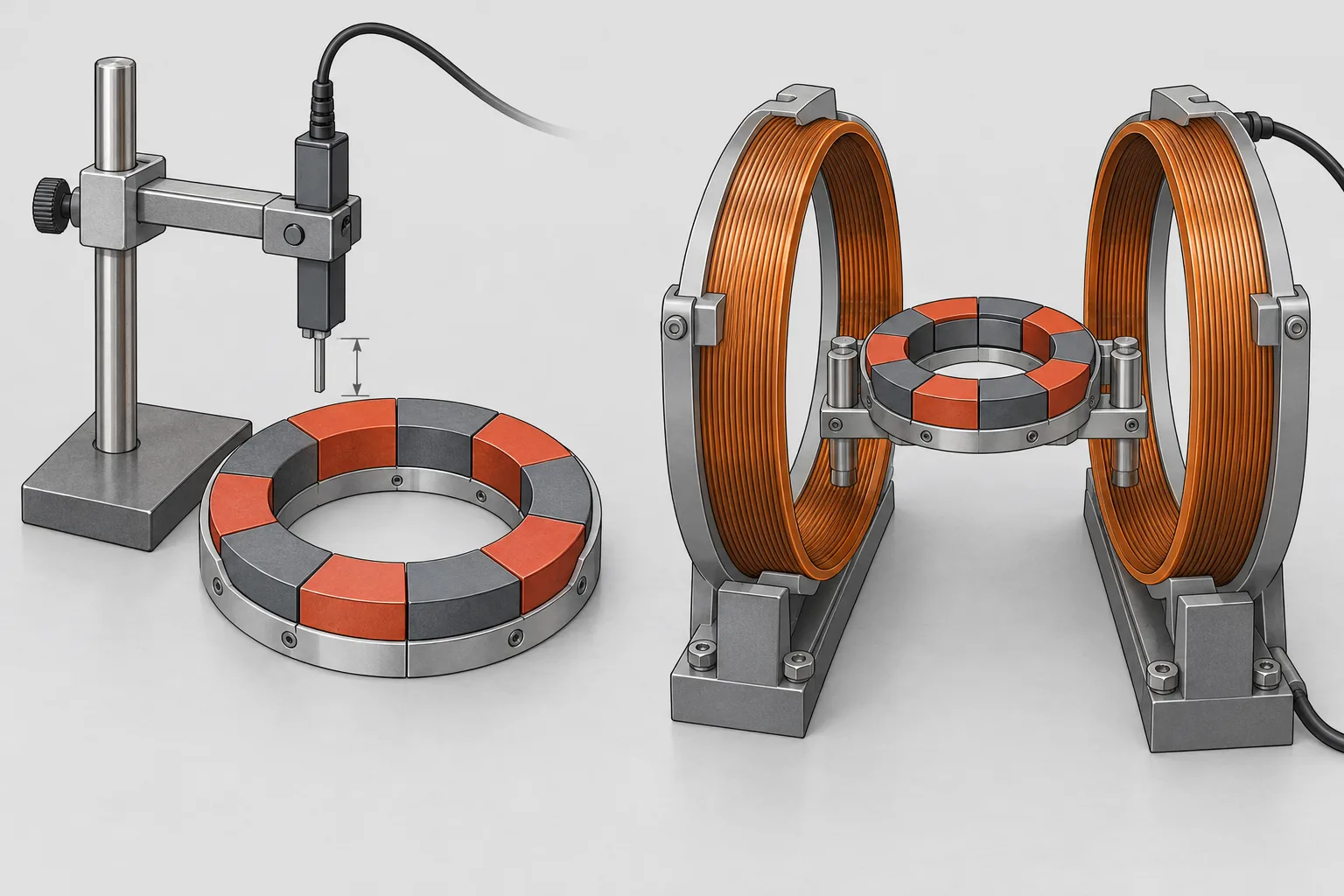
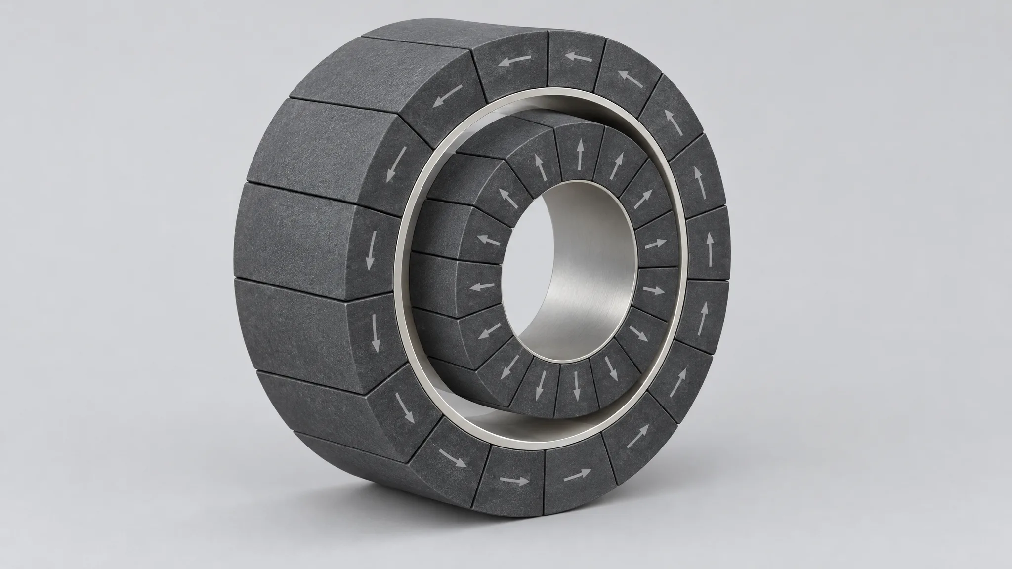
On a single magnet or segment, an irreversible loss is the difference between that piece's magnetic moment before and after the agreed thermal exposure, both read at the same reference temperature — read hot and then cold, and a temperature effect is being compared with a demagnetization effect. It is not a difference against a nominal figure on a drawing, and it is not one gauss reading taken by hand. A finished multipole ring is the harder case, because the moment of the whole part sums sectors that oppose each other and a loss in one of them can hide in that sum; there the evidence is the three-dimensional field map and readings taken across the working face, compared position by position with the same part at the same reference condition before the exposure.
At batch level the record is wider. Each batch is scanned in three dimensions and the resulting field map is checked for gap flux density, how close the waveform comes to a sine, and its harmonic content; dimensional, flux and coating checks run alongside, with a temperature-demagnetization check where the order calls for one, and field, dimensional and coating reports can be issued with that scope. Which checks run, on how many parts, how often, and what the report must contain are agreed per order rather than carried over — that is how the scope of a batch check is written — and it is the record a later spare has to answer to: a replacement rotor is interchangeable only when the field acceptance went onto the drawing, as it is for the matched pair in a magnetic coupling.
One more number belongs in the same conversation, and it is not the same quantity. Across batches we hold the variation in gap flux density through tooling and magnet sorting, and the figure we discuss is ±3–5%, subject to the design and to the conditions agreed for the order. That figure compares one batch with another; a demagnetization limit compares a part with itself before and after an exposure. Read a batch report against the wrong one of the two and it tells you nothing about either.
What do you send us so the check means something?
Six inputs, and the drawing already carries most of them:
- The magnet temperature at its worst point, steady and transient.
- The demagnetizing field there, including the fault case.
- The circuit permeance at the worst gap.
- The flux or moment you will accept after the exposure you name.
- The exposure the batch has to be held to.
- Prototype and production quantities, with the checks and the record the order needs.
From those, our engineering review takes the material and the magnetic circuit together, and comes back with a grade, a working point at temperature, and an acceptance item that can actually be measured. Put the six on the drawing or in the RFQ and the item that comes back is one a second batch can be held to as well; send the drawing and the operating conditions to sales@neolune.com and the review starts from the hot point rather than from a grade number.